GB
GB
32
33
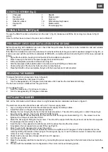
LEFT-HAND BARRIER
To convert the barrier from RIGHT-HAND to LEFT-HAND, proceed as follows:
1.
Move the spring from the right-hand to the left-hand position (fig. G1)
2.
Swap the motor wires on the control unit (35 with 36, next page)
3.
Swap wires 14 and 16 (electric limit switch)
Then proceed with installation.
FCS
D
-
TPR.OPEN
FotoRIC.
JOLLY
SLAVE
RIC.AUT.
PRELAMP.
REG.VEL.
P/P
U
S
1
JCC
LD1
RS
P/P
PA
TEST
TR1
FCS
C2
24FT
24V
NA
COM
NC
Slave
LDA
TPR
+
-
P/P
PA
PC
C
CC
STP
FT
CSB
+
-
+
-
-
+
D
M
M
FC1
FC2
C1
ON
CC
STP
FT
TPR
+
-
Reset
A
N
T
.
P3
1
2
3
4
5
6
7
8
9
10
11
12
P/P
STOP
PROG.
SCHEDA RADIO OC
+
1
O
N
+
+
23
1
2
3
4
22
21
20
19
18
5
7
8
13
12 11
14
15
16
9
10
6
17
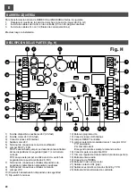
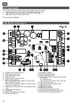
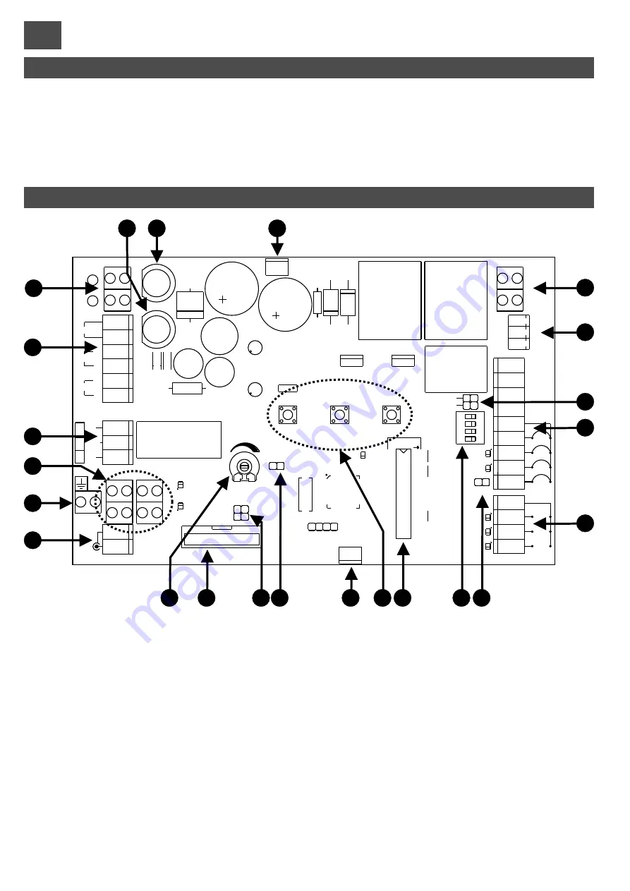
DESCRIPTION OF PARTS (Fig. H)
1)
Auxiliary circuit fuse 24V (2A fast)
2)
Motor fuse 24V (10A fast)
3)
Internal LED light connector
4)
Motor output 24V
5)
Encoder connection terminal board
6)
TEST and FCS jumpers
TEST: removing this jumper disables the safety inputs
(item 7) with barrier closed.
FCS: remove this jumper if a safety microswitch is used
on the door (input 26 - NC)
7)
Safety device and control system power supply terminal
board
8)
Control input terminal board
9)
Jumper JCC
10) Safety device disabling dip-switches
11) Functions dip-switches
12) Programming buttons
13) Internal LED light connector
14) Control unit RESET jumper
15) OC2 receiver channel 1 model selection jumper:
P/P: stepping
PA: open command
The second channel is always close command.
16) OC2 receiver connector
17) Opening deceleration regulator trimmer
18) Radio antenna input
19) GROUND connection
20) Motor limit switch input
21) US1 (multi-purpose) output contact
22) Bar lights output, SLAVE and TPR controls
23) Control unit power supply input 24Vdc
Fig. H
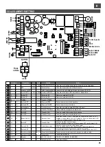
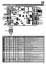
ELECTRICAL CONNECTIONS
FCS
D
-
TPR
FotoRIC.
JOLLY
SLAVE
RIC.AUT.
PRELAMP.
REG.VEL.
P/P
U
S
1
JCC
LD1
RS
P/P
PA
TEST
TR1
FCS
C2
24FT
24V
NA
COM
NC
Slave
LDA
TPR
+
-
P/P
PA
PC
C
CC
STP
FT
CSB
+
-
+
-
- BLUE wire
+ GREEN wire
D WHITE wire
FC1
FC2
C1
ON
CC
STP
FT
TPR
+
-
Reset
A
N
T
.
P3
1
2
3
4
5
6
7
8
9
10
11
12
P/P
STOP
PROG.
SCHEDA RADIO OC
+
1
O
N
+
+
24
V
d
c
M
O
TO
R
M
1
2
3
4
5
6
7
8
9
1
0
1
1
1
2
1
3
1
5
1
4
1
6
1
7
1
8
1
9
2
0
2
1
2
2
2
3
2
4
2
5
2
6
2
7
2
8
2
9
3
0
3
1
3
2
3
3
3
4
3
5
3
6
EN
CO
DE
R
+
-
+
-
B
ar
lig
h
t
o
u
tp
u
t
o
u
tp
u
t U
S
1
8A
2
30
V
C2
FC1
FC2
C1
1
3
1
5
1
4
1
6
Limit switch
closure
Opening key
FT
STOP
Closing edge
Door contact
CLOSE button
OPEN button
P/P button
Alimentazione
fotocellule
Morsetto n.
1
5
7
9
10
10
11
12
13
14
15
16
17
18
19
22
20
22
21
23
27
24
27
25
27
26
27
28
29
30
31
32, 33, 34
35
36
TPR
comando SLAVE
Luci ASTA
Uscita US1
Uscita US1
TERRA
Contatto NC
Contatto NC
Antenna Radio
NO button
NO button
NO button
Edge 8K2 / N.C.
NC button
NC contact
N.C. contact
Auxiliary devices
Auxiliary devices
Encoder
Motor
24Vdc
24Vac
24V
100 mA
control unit power supply
Power failure
SLAVEC control output
BAR lighting
NC multifunction output
NO multifunction output
GROUND contact
OPEN limit switch
CLOSE limit switch
Stepping control
Close command
Open command
Closing edge
Stop command
Closing photocell
Door contact
Photocell power supply
Power supply
32 - / 33 + / 34 D
Motor output 24V
Dispositivo
V
I max
Funzione
Note
Connect to transformer secondary
Connect to power supply output of power supply box
Connect to control unit of second (SLAVE) barrier
Connect to bar LED lights, if installed
Limit switch near open position
Limit switch near closed position
Connect to an antenna for 433 MHz (50 Ohm)
See dip-switch configuration table
Starts of opening of the barrier
Starts closure of the barrier
Input enabled for closur. Option of connecting 8K2 edges (JCC closed) or
an N.C. contact (JCC open). If not used, open JCC and set dip-switch CC
(dip-switch 3 of item 10) ON
Cuts out all functions
If not used, set dip-switch STP (dip-switch 2 of item 10) ON
Reverses direction during closure.
If not used, set dip-switch FT (dip-switch 1 of item 10) ON
Connect this input to the door safety microswitch
If not used, place a jumper across the input (wire between 26 and 27)
Power only present when barrier is not closed
Permanent voltage
Connection to motor
2
3
4
6
8
22
24Vdc
1A max
24Vdc
1
A
m
a
x
.
Contact data: 8A 230V
Contact data: 8A 230V
10 A
32 BLUE, 33 GREEN, 34 WHITE
A
n
te
n
n
a
Summary of Contents for RAPPER4TL
Page 4: ...I F E GB D NL 270 Fig D min 200 mm 310 240 m in 400 227 160 min 350 Fig E1 Fig E2 4...
Page 5: ...I F E GB D NL Fig F Fig G 4 5...
Page 54: ...NOTE...
Page 55: ......


