GB
GB
34
35
O
N
1
2
O
N
1
2
O
N
1
2
O
N
1
2
1
2
3
9
5
11
6
12
7
8
4
10
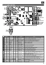
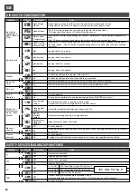
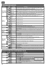
Function
n. Off On
Description
Notes
During opening, press the P/P button to stop the barrier; press again to close.
During closure, press the P/P button to stop the barrier; press again to open.
This mode can be used to operate a courtesy light.
Access from cycle start a programmable time after closure.
If the P/P button is pressed during opening, the barrier stops then closes.
If it is pressed during closure, the barrier stops then opens.
Contact for controlling a flashing light, frequency 2 Hz.
Pressing the P/P button during opening has no effect. Pressing the P/P button during a pause has no
effect.
If the P/P button is pressed during closure, the barrier stops for a few seconds then opens.
Output active during opening, closing and pause.
Pressing the P/P button during opening has no effect. If the P/P button is pressed during a pause,
the barrier closes. if the P/P button is pressed during closure, the barrier stops for a few seconds
then opens.
Output active with barrier not closed.
medium-low
Electric
interlock
contact
Always opens
“Condominium”
low
Barrier status
signalling
contact
Off
Off
Off
Off
Off
On
On
On
On
On
Opens-Closes
with no reversal
during opening
medium-high
Flashing light
contact
Opens-Closes
high
Courtesy light
contact
Opens-Stops-
Closes
The flashing light operates together with the motor.
Function disabled
After complete opening, the barrier can only be closed by a manual command.
Function disabled.
Function disabled
The flashing light operates 5 seconds before any operation.
The barrier remains open in the event of a blackout. When the power returns the barrier closes if
dip 6 is ON.
After complete opening, the barrier closes after a programmed pause time.
Tripping of the photocell reduces the pause time to 2 seconds, regardless of the setting.
The control unit performs the commands received from a MASTER control unit
3
4
9
1
0
3
4
9
1
0
3
4
9
1
0
3
4
9
1
0
Preflash
Black out
opening
Output US1
(multipurpose)
mode). Clean
contact
Barrier speed
Input mode
Stepping and
Radio Channel
(CH1)
Re-closure
Timer
Closure
photocell
Not used
SLAVE
Operation
Function
n. Off On
Description
Notes
1
2
3
4
OFF
OFF
OFF
OFF
ON
ON
ON
ON
With photocell installed
With STOP input used
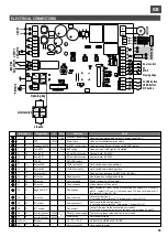
Connect transformer secondary to terminals 3 and 4.
If mains power fails, the barrier opens (with dip 11 ON and with use of buffer battery).
Disables photocell input
Disables STOP input
Function disabled
FT
STP
CC
TPR
With Close Edge (type NC) input used
Disables Close Edge input
DIP-SWITCH CONFIGURATION
JCC in OFF
With Close Edge (type 8K2) input used
JCC in ON
JCC: item 9 di fig. H
JCC in OFF
opening time 3 sec. approx.
opening time 4 sec. approx.
opening time 6 sec. approx.
opening time 8 sec. approx.
SAFETY DEVICE DISABLING DIP-SWITCHES
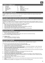
PROGRAMMING THE OPEN AND CLOSED POSITIONS
The SNAP4 barrier is programmed by default for use with opening at 90 degrees and closure at 0 degrees.
If the opening and/or closing point has to be adjusted due to special installation requirements, proceed as follows:
For the opening point:
1.
Disconnect the power supply to the control unit
2.
Set the automatic re-closure dip-switch 6 on OFF
3.
Loosen the locknut and temporarily lift the rubber opening vibration damper
4.
Power up the control unit
5.
Press the P/P button; the bar opens
6.
Hold down the PROG/STOP button for about 3 sec. until LED LD1 illuminates
7.
Press P/P repeatedly to move the point in the opening direction or P3 for the closing direction
8.
Press PROG/STOP to save the point selected
9.
Put the rubber vibration damper against the rod.
10. Release the rod and move it to its point of equilibrium (about 45 degrees)
11. Lower the rubber vibration damper by about another 2 millimetres and lock in place with the locknut
12. Return dip-switch 6 to ON to re-enable automatic re-closure
13. Restore power to the control unit
For the closure point:
1.
Press P/P to open the barrier
2.
Disconnect the power supply to the control unit
3.
Set the automatic re-closure dip-switch 6 on OFF
4.
Undo the locknut and temporarily lift the rubber opening vibration damper
5.
Power up the control unit
6.
Press the P/P button; the bar closes
7.
Hold down the PROG/STOP button for about 3 sec. until LED LD1 illuminates
8.
Press P/P repeatedly to move the point in the opening direction or P3 for the closing direction
9.
Press PROG/STOP to save the point selected
10. Put the rubber vibration damper against the rod.
11. Release the rod and move it to its point of equilibrium (about 45 degrees)
12. Lower the rubber vibration damper by about another 2 millimetres and lock in place with the locknut
13. Return dip-switch 6 to ON to re-enable automatic re-closure
14. Restore power to the control unit
This operation must be carried out with the barrier closed:
1.
Press P3 and hold it down until LED LD1 illuminates (it flashes once a second)
2.
Press P/P to start counting of the pause time. LED LD1 changes its flashing mode.
3.
After the pause time required, press P/P again to memorise it. LED LD1 will remain on steadily for a couple of
seconds and then go out.
PROGRAMMING THE COURTESY LIGHT TIME (output US1 with dip-switches 9 and 10 OFF)
This operation must be carried out with the barrier closed:
1.
Press P3 and hold it down until LED LD1 illuminates (it flashes once a second)
2.
Press P3 again; LED LD1 will now flash twice every second. 2)
3.
Press P/P to start counting of the courtesy light time. LED LD1 changes its flashing mode.
4.
After the time required has passed, press P/P again to memorise it. LED LD1 will remain on steadily for a couple of
seconds and then go out.
DISPLAYING THE TOTAL COUNT OF BARRIER OPERATIONS
This operation must be carried out with the barrier closed:
1)
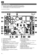
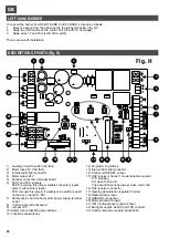
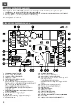
Hold down P3 to reset the control unit by short-circuiting the RESET jumper (14, fig. H) for a moment.
2)
The yellow LEDs will flash 6 times, after which the number of operations will be displayed.
PROGRAMMING THE PAUSE TIME
Summary of Contents for RAPPER4TL
Page 4: ...I F E GB D NL 270 Fig D min 200 mm 310 240 m in 400 227 160 min 350 Fig E1 Fig E2 4...
Page 5: ...I F E GB D NL Fig F Fig G 4 5...
Page 54: ...NOTE...
Page 55: ......


