Telecast Fiber Systems
7
AUDIO
DATA
1
CLOCK
COAX
DATA I/O
SLO
DC
INPUT
12-24 VDC
2
3
4
OPTICAL
1
3
5
7
9
11
13
15
2
4
6
8
10
12
14
16
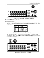
Figure 6. ST Type Optical Connectors, Rear Panel
Electrical Connections
Audio Connections
Audio I/O is via 3-pin XLR connectors with industry standard wire locations. See Table
3 and Figure 7.
Pin
Signal
1
Ground
2
Balanced I/O (-)
3
Balanced I/O (+)
Table 3. XLR Audio I/O Cable Connections
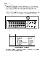
The XLR connectors are on the rear panel as shown in Figure 7. Transmitter XLR
connectors are female Switchcraft type E3FST-AU. Receiver XLR connectors are male
Switchcraft type E3MST-AU.
2
3
1
1
3
2
or
TX (Female)
RX (Male)
AUDIO
DATA
1
CLOCK
COAX
DATA I/O
SLO
DC
INPUT
12-24 VDC
2
3
4
OPTICAL
1
3
5
7
9
11
13
15
2
4
6
8
10
12
14
16
Figure 7. XLR Connectors, Rear Pane
Summary of Contents for Adder 161
Page 2: ...Adder 161 ii...
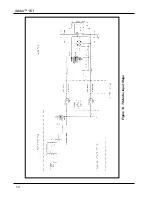
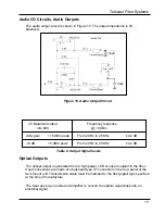
Page 18: ...Adder 161 Figure 14 TX Audio Input Stage 14...
Page 25: ...Telecast Fiber Systems 21...


