Adder™ 161
Pin Number
Connectors 1, 2
Connectors 3, 4
1
RS-422 in (-)
no connection
2
contact out
contact out
3
gnd
gnd
4
RS-232 out
no connection
5
RS-422 out (-)
no connection
6
RS-422 in (+) RS-232 in
no connection
7
contact out
contact out
8
contact in
contact in
9
RS-422 out (+)
no connection
Table 4. Digital Cable Connections
The digital I/O connector on both the rack mount and portable units, TX and RX, is an
AMP 747905-2, DB-9 sub miniature female.
Digital Connections
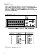
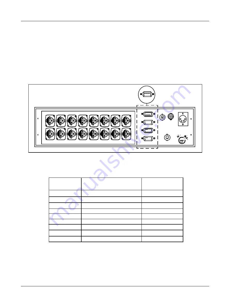
Digital signal connections are made via the DB-9 connectors as shown in Figure 8.
The connection specifications are listed in Table 4. A 110 terminating resistor placed
across the balanced inputs may be needed if cable lengths are in excess of 6
feet (if using 110 twisted pair). Serial communications can be RS-232 at one end and
RS-422 at the other, if desired.
Contact closure input to the TX is activated by connecting it to ground or to a TTL logic
0 signal level. Contact closure output from the RX is established by an isolated,
normally open, dry contact.
AUDIO
DATA
1
CLOCK
COAX
DATA I/O
SLO
DC
INPUT
12-24 VDC
2
3
4
OPTICAL
1
3
5
7
9
11
13
15
2
4
6
8
10
12
14
16
5
1
6
9
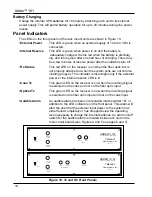
Figure 8. Rack Mount, DB-9 Connectors, TX and RX, Rear Panel
8
Summary of Contents for Adder 161
Page 2: ...Adder 161 ii...
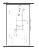
Page 18: ...Adder 161 Figure 14 TX Audio Input Stage 14...
Page 25: ...Telecast Fiber Systems 21...


