Telecast Fiber Systems
48 VDC Phantom Power
A 48 VDC microphone bias supply is available to the TX units. The voltage is supplied
from a DC/DC converter that is connected through 10 K to pins 2 and 3 of the XLR
connector. The XLR connector circuit board has 16 switches for enabling this power to
the microphones. These switches are accessible by removing the top cover of the rack.
The switches are numbered on the XLR circuit board.
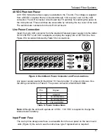
Line Power Connection
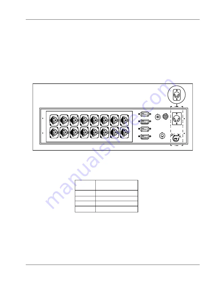
Insert the 4-pin XLR connector from the standard Telecast power supply into the Adder
161 DC INPUT 12-24 VDC receptacle, and plug the supply into a 120 VAC line. See
Figure 9 for locations followed by Table 5 for connections.
AUDIO
DATA
1
CLOCK
COAX
DATA I/O
SLO
DC
INPUT
12-24 VDC
2
3
4
OPTICAL
1
3
5
7
9
11
13
15
2
4
6
8
10
12
14
16
1
4
3
2
Figure 9. Rack Mount Power Connector and Fuse Locations
Any power supply used with the Adder 161 must provide 1.5 amps continuous. Use
the wiring connections in Table 5. The power connector is Switchcraft D4M.
1
ground
2
no connection
3
no connection
4
+12 to 24 VDC
Pin
Signal
Table 5. Power Connections
Note: Although the units will operate at 12 VDC, 13.8 VDC is required to charge the
internal reserve battery.
Input Power Fuse
The 2-amp time delay power fuse is accessible from the rear panel on the rack mount
units (Figure 9). Be sure to use the same fuse type if replacement is required.
9
Summary of Contents for Adder 161
Page 2: ...Adder 161 ii...
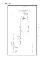
Page 18: ...Adder 161 Figure 14 TX Audio Input Stage 14...
Page 25: ...Telecast Fiber Systems 21...


