Adder™ 161
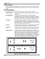
Figure 10. Tx and Rx Front Panels
COAX
TRANSMISSION
EXTERNAL
ON
OFF
INTERNAL
RESERVE
POWER
RX STATUS
OPTICAL
AUDIO MULTIPLEXER — RECEIVER
Telecast
Fiber Systems, Inc.
Made in U.S.A.
ADDER
161
EXTERNAL
ON
OFF
INTERNAL
RESERVE
POWER
MASTER
SLAVE
MODE
AUDIO MULTIPLEX ER — TRANSMITTER
ADDER
161
Telecast
Fiber Systems, Inc.
Made in U .S.A.
Battery Charging
Charge the internal UPS batteries for 16 hours by attaching each unit to its external
power supply. This will permit battery operation for up to 20 minutes during line power
losses.
Panel Indicators
The LEDs on the front panels of the rack mount units are shown in Figure 10.
•External Power
This LED is green when an external supply of 12 to 24 VDC is
connected.
•Internal Reserve
This LED is green when power is on and the battery is
adequately charged. It turns red when the battery is discharg
ing, and turns green after one half hour of charging. There may
be a few minutes of reserve power after the indicators turn off.
•Rx Status
This red LED on the receiver is on when the fiber optic link is
not properly attached or when the system units are not commu
nicating properly. This indicator is meaningful only if the external
power or the internal reserve LED is lit.
•Coax Tx
This green LED on the receiver is on when the incoming signal
is selected on the coax and not on the fiber optic input.
•Optical Tx
This green LED on the receiver is on when the incoming signal
is selected on the fiber optic input and not on the coax input.
•Audible Alarm
An audible alarm has been incorporated into the Adder 161 in
addition to the LED indicators on the front panel. This alarm will
alert the user that the external input power to the system has
either failed completely or has dropped below the operating
level necessary to charge the internal batteries. An alarm on/off
switch for the audible alarm is located inside each unit on the
main circuit boards (see Figures 4 and 5 on pages 6 and 7).
10
Summary of Contents for Adder 161
Page 2: ...Adder 161 ii...
Page 18: ...Adder 161 Figure 14 TX Audio Input Stage 14...
Page 25: ...Telecast Fiber Systems 21...


