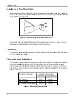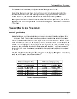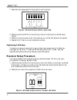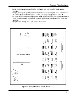
Adder™ 161
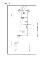
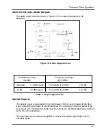
Audio I/O Circuits, Audio Inputs
Audio inputs and outputs are on sixteen separate XLR connectors, each of which is
connected to a circuit as shown in Figure 14.
Inputs can be set to have a balanced input impedance 600 or 10 K.
The audio
input circuit shown in Figure 14 can accept a wide range of signal levels. Refer to
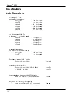
“Specifications” for details.
+5
5 9 4 8 3 7 2 6 1
Data I/O
IN
OUT
-
-
+
+
10k
100k
.1
74HC14A
Data to
Multiplexer
+5
39k
10k
10k
39k
22pf
22pf
10k
10k
MAX909
+
-
Data to
Multiplexer
+5
-5
BAT54S
1
2
3
4 5
6
7
8
Figure 12. Digital Input Circuit (Connectors 1 and 2 only)
Digital I/O Circuits, Data Connectors 1 and 2
Digital I/O Circuits, Data Connectors 3 and 4
These connectors have contact and relay closure capability only. Digital data can only
be accepted and sent on connectors 1 and 2. The contact input and relay output
circuits are as described above. The pin wiring for connector 3 and 4 closure circuits is
the same as on connectors 1 and 2.
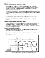
The TX digital input buffer circuit shown in Figure 12 accepts both data signals
(RS-232, RS-422 and RS-423) and contact closures and delivers this information to
the multiplexer. The data handling portion of the circuit is connected only to DB-9
subminiature data connectors 1 and 2.
It also accepts a contact closure indicated by the switching of pin 8 to ground level, pin
3. This can also be accomplished by a TTL connection closure with pin 3 as the ground
reference.
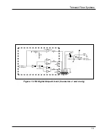
The RX digital output buffer circuit shown in Figure 13 accepts the demultiplexed data
and contact closure signals and provides them at appropriate levels to the DB-9
subminiature data connector.
The output closure output is via an SPST-NO relay; this closure is not ground
referenced.
12
Summary of Contents for Adder 161
Page 2: ...Adder 161 ii...
Page 18: ...Adder 161 Figure 14 TX Audio Input Stage 14...
Page 25: ...Telecast Fiber Systems 21...

