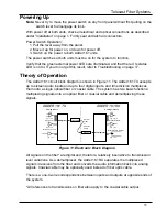


Telecast Fiber Systems
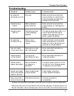
Troubleshooting
*Replace the internal Ni-Cad battery every two years as part of routine maintenance.
Whenever there seem to be problems, first verify the adequacy of optical power at the
Rx end of the fiber. Use an optical power meter such as the one in the Accessory List.
Symptoms
Possible Cause
Corrective Action
No operation,
No power
Make sure both units have their
all indicators are off
power switches on, and that their
external supplies are delivering
between13.8 and 24 VDC.
internal reserve
Battery depleted
Make sure both units have their
LED off
power switch off
power switches on. Recharge the
battery.
internal reserve
External power loss
The light becomes green after a 1/2
LED red
or internal battery
hour of use with the AC power
depleted.
adapter. If the light does not turn
green, replace the battery.
No operation
Fiber or coax
Check for broken or disconnected
rx status LED on
communications
fibers and faulty wires, or that the
failure
Adder 161 unit on the other end is
powered on and operational.
Very low output
Microphone on input
Move internal DIP switches to a
on one audio chan.
with 0 dB selected
higher gain setting.
Signal distorted
Line input with
Move internal DIP switches to a
on one channel
gain setting too high
lower gain setting.
Internal reserve
Reserve battery is
Connect to power source of 13.8 to
battery fails quickly
not charged, or
24 VDC for 16 hrs. Replace battery
has failed
if charging is not successful.
System goes dead
reserve battery dead
Check battery connection.
as soon as external
or disconnected
If okay, replace the battery.*
power is removed
Noisy signal with a
A/D input level too low
Increase input gain on
low level input source
preamplifiers.
17
Summary of Contents for Adder 161
Page 2: ...Adder 161 ii...
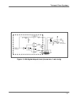
Page 18: ...Adder 161 Figure 14 TX Audio Input Stage 14...
Page 25: ...Telecast Fiber Systems 21...


