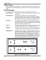
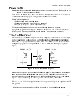
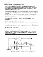

Adder™ 161
Warranty
LIMITED WARRANTY STATEMENT
Telecast Fiber Systems, Inc. (“Telecast”) expressly warrants to Buyer that the Products supplied shall be free
from defects in materials and workmanship for a period of 12 months following the date the Products are
delivered to Buyer (the “Warranty Period”). Telecast's liability under this limited warranty shall be limited, at its
option, to providing refund of purchase price for Products, or replacing or repairing Products shown to be
defective either in materials or workmanship. Buyer's sole and exclusive remedy for breach of warranty shall be
such refund, replacement or repair.
A claim of defect in materials or workmanship in any Product shall be allowed only when it is submitted in writing
to Telecast Fiber Systems, Inc. within seven days after discovery of the defect, and in any event within the
Warranty Period. No claim shall be allowed in respect of any Product which has been altered, neglected,
damaged or stored in any manner which adversely affects it. In order to obtain service under the terms of this
warranty, Distributor’s customer or Distributor must notify Telecast of the defect prior to the expiration of the
applicable warranty period and obtain a Return Authorization Number from Telecast. In no event may products be
returned to Telecast or to Distributor for warranty service without having obtained from Telecast a Return
Authorization Number.
This limited warranty applies only to new and unused Products delivered to Buyers located within the United
States of America, or to international Buyers if sold through an authorized Distributor organization, and shall not
extend to any equipment not manufactured by Telecast Fiber Systems, Inc., even though such equipment may be
sold or operated with the Products. In addition, this limited warranty shall be void and of no further force or effect
whatsoever if the Product is repaired or modified by any person other than an authorized representative of
Telecast Fiber Systems, Inc. without the consent of Telecast Fiber Systems, Inc. This warranty shall not apply to
any defect, failure or damage caused by improper use or inadequate maintenance and care. Nor shall this
warranty apply to any damage caused in whole or in part by attempts by personnel other than Telecast’s
personnel, as approved in advance in accordance with the foregoing provisions, to open, install, repair, or
service the Product; nor to damage resulting from improper connection with incompatible equipment; nor to
damage to a unit which has been modified by personnel other than Telecast personnel.
Products returned to Telecast for warranty service shall be shipped, freight prepaid to Telecast. Telecast will
return the repaired product or ship a replacement, freight prepaid, to either Distributor or Distributor’s customer,
as requested by Distributor’s customer, at a location within the United States or, at Telecast’s option, to
Distributor’s location in the case of international sales.
This limited warranty shall also apply to Products that replace defective Products and Products that have been
repaired by authorized representatives of Telecast Fiber Systems, Inc., but only for the original Warranty Period.
The Warranty Period shall not be extended by reason of defect, or any period of time during which the Product is
not available to Buyer because of defects or repairs, without the express written consent of Telecast Fiber
Systems, Inc.
EXCEPT FOR THE EXPRESS LIMITED WARRANTY AGAINST DEFECTS IN MATERIALS AND WORKMANSHIP
CONTAINED HEREIN, TELECAST FIBER SYSTEMS, INC. MAKES NO WARRANTY OF ANY KIND WHATSOEVER,
EXPRESS OR IMPLIED, AND ALL WARRANTIES OF MERCHANTABILITY, FITNESS FOR A PARTICULAR PURPOSE,
AND OTHER WARRANTIES OF WHATEVER KIND ARE HEREBY DISCLAIMED BY TELECAST FIBER SYSTEMS, INC.
THIS LIMITED WARRANTY SETS FORTH EXCLUSIVELY ALL OF TELECAST FIBER SYSTEMS, INC.'S LIABILITY IN
CONTRACT OR OTHERWISE IN THE EVENT OF A DEFECTIVE PRODUCT.
WITHOUT LIMITATION ON THE FOREGOING, TELECAST FIBER SYSTEMS, INC. EXPRESSLY DISCLAIMS ANY
LIABILITY WHATSOEVER FOR ANY DAMAGES INCURRED DIRECTLY OR INDIRECTLY IN CONNECTION WITH THE
SALE OR USE OF, OR OTHERWISE IN CONNECTION WITH, THE PRODUCT, INCLUDING WITHOUT LIMITATION,
LOSS OF PROFITS AND SPECIAL, INCIDENTAL OR CONSEQUENTIAL DAMAGES, WHETHER CAUSED BY
NEGLIGENCE OR OTHERWISE, REGARDLESS WHETHER TELECAST HAS BEEN GIVEN ADVANCE NOTICE OF
THE POSSIBILITY THEREOF.
THIS WARRANTY IS GIVEN BY TELECAST IN LIEU OF ANY OTHER WARRANTY EXPRESSED OR IMPLIED.
20
Summary of Contents for Adder 161
Page 2: ...Adder 161 ii...
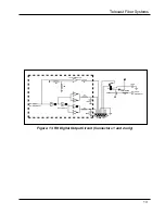
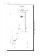
Page 18: ...Adder 161 Figure 14 TX Audio Input Stage 14...
Page 25: ...Telecast Fiber Systems 21...


