Telecast Fiber Systems
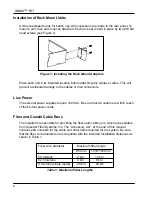
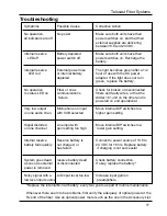
The system units are factory configured for the fiber type to be used.
Inspect the fiber ends and clean them with clean, dry compressed air or with Kim-
Wipes that have been wet with isopropyl alcohol. Fingerprints or other dirt on the
optical connector end surfaces will reduce the received optical signal level.
If the system is to be used with a coaxial cable instead of an optical fiber, use Belden
type 8281, 75 coax, or equivalent. The maximum length for coax cable is 500 meters
(1640 feet).
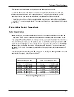
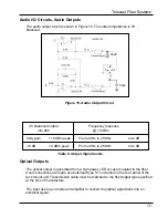
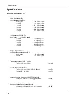
600 balanced (low Zin)
10 K balanced (high Zin)
Unity
+18 dBm peak
Unity
+16 dBV peak
+10 dB +8 dBm peak
+10 dB
+6 dBV peak
+20 dB -2 dBm peak
+20 dB
-4 dBV peak
+30 dB -12 dBm peak
+30 dB
-14 dBV peak
+40 dB -22 dBm peak
+40 dB
-24 dBV peak
+50 dB -32 dBm peak
+50 dB
-34 dBV peak
Audio Signal Setup
Note: Setting up the internal switches on the rack mount unit requires removal of its
top cover. The DIP switches should be set before installing the units in their racks.
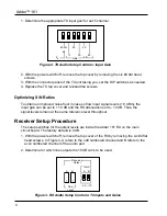
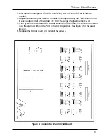
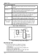
The setup DIP switches for line or mic input levels are inside the Adder 161 TX on the
main circuit board. There are 16 switches, one for each channel. A representative DIP
switch is shown in Figure 2. Setup steps are not required if all inputs are at the factory
default of 600, 0 dB gain (line level). Setup steps are required if mic level inputs will
be used, if 10 K input impedance is required, or if an optional 10 dB boost is desired
at the TX.
The RX output default setting is 0 dB, unity gain. In the figures throughout this manual,
each switch is shown in its default position.
Table 2: Input Signal Levels
Transmitter Setup Procedure
3
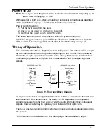
Summary of Contents for Adder 161
Page 2: ...Adder 161 ii...
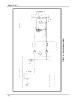
Page 18: ...Adder 161 Figure 14 TX Audio Input Stage 14...
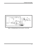
Page 25: ...Telecast Fiber Systems 21...


