Telecast Fiber Systems
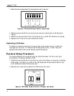
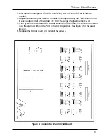
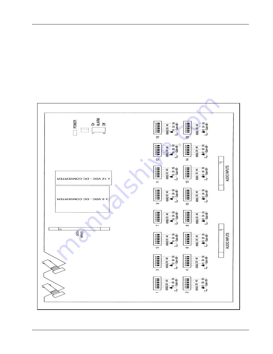
3. With the connector panel of the RX unit facing you, move the DIP switches as
needed.
4. Adjust the output signal levels to normalize the outputs using the Fine Level trim pot
in each output circuit of the Adder 161 RX. The range of adjustment is ± 2 dB.
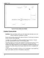
5. If the system is to be used with coaxial cable rather than fiber, move the small switch
near the alarm switch on the PCB to the COAX position. See figure 5 for the exact
location.
6. Replace the RX top cover and reinstall the screws.
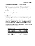
Figure 4. Transmitter Main Circuit Board
5
Summary of Contents for Adder 161
Page 2: ...Adder 161 ii...
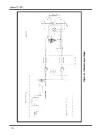
Page 18: ...Adder 161 Figure 14 TX Audio Input Stage 14...
Page 25: ...Telecast Fiber Systems 21...


