Adder 882
4
1 April 1999
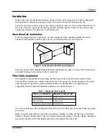
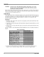
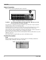
WARNING Do NOT use the Adder 882 optical output for this purpose. Never look
directly into the end of the optical Þber while either end of the system is
operating. Eye damage is possible.
Inspect the Þber ends and clean them with clean, dry compressed air or with Kim-Wipes that have
been wet with isopropyl alcohol. Fingerprints or other dirt on the optical connector end surfaces
will reduce the received optical signal level.
Audio Setup
The setup switches for line
or microphone inputs levels are inside the Adder 882. Setup steps are
not
required if all inputs are at the factory default 600
W,
0 dB gain, line level. Setup
is
required if
microphone inputs are used, if 5 k
W
input impedance is required, or if the optional 10 dB
boost/cut is desired on line inputs.
Procedure
1. Determine which inputs will be connected to microphones and for which line I/O the 10 dB
boost/cut is to be used.
2. Copy Table 2 and Þll in the required I/O characteristics. Recopy the original table for use with
other hookups.
3.
With the power switch off
, take off the top cover of the unit by removing the #4 ßat head screw
at each corner.
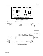
In Figure 5,
A
refers to the odd numbered channel and
B
refers to the even numbered channel of
the pair.
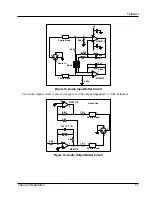
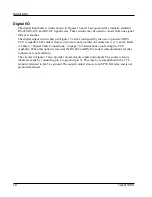
4. With the rear of the unit facing you (connector end), move the slide switches shown in
Figures 5 and 6 to match the settings in Table 2. The controls are arranged in pairs.
Table 2. Audio Inputs
Channel Number
UNIT A SWITCH SETTING
1
2
3
4
5
6
7
8
MIC
IN
(0 or +40 db gain)
LINE
IN
(0 or +10 db gain)
INPUT IMPEDANCE
(600
W
or 5 k
W
)
LINE
OUT
(0 or
-
10 db gain)
UNIT B SWITCH SETTING
1
2
3
4
5
6
7
8
MIC
IN
(0 or +40 db gain)
LINE
IN
(0 or +10 db gain)
INPUT IMPEDANCE
(600
W
or 5 k
W
)
LINE
OUT
(0 or
-
10 db gain)


