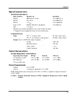
Adder 882
6
1 April 1999
Optical Connections
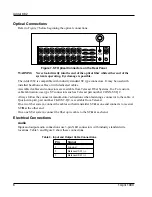
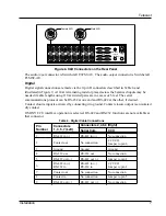
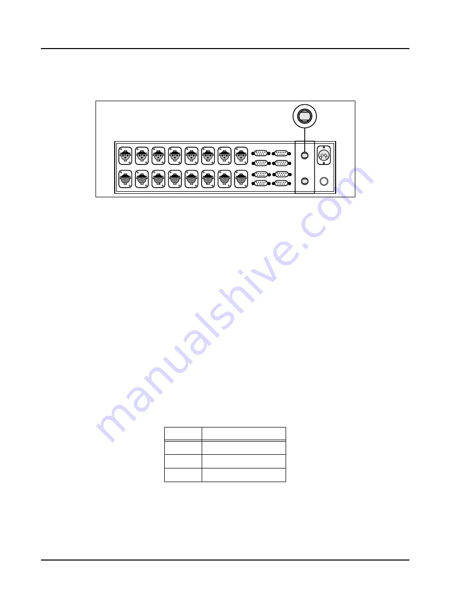
Refer to Figure 7 before beginning the optical connections.
Figure 7. ST Optical Connectors on the Rear Panel
WARNING Never look directly into the end of the optical Þber while either end of the
system is operating. Eye damage is possible.
The Adder 882 is compatible with industry standard ST type connectors. It may be used with
installed backbone cables or with dedicated cables.
Assembled cables and connectors are available from Telecast Fiber Systems, Inc. For custom
cable fabrication, use type ST connectors such as Telecast part number CONN-ST-QC.
Always follow the connector manufacturerÕs directions when fastening a connector to the cable. A
Quick-crimp kit, part number CKIT-ST-QC, is available from Telecast.
On a two Þber system, connect the cables so that transmitter ST
A
at one end connects to receiver
ST
B
at the other end.
On a one Þber system, connect the Þber optic cable to the ST
A
at each end.
Electrical Connections
Audio
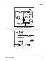
Input and output audio connections use 3-pin XLR connectors with industry standard wire
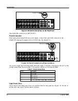
locations. Table 3 and Figure 8 show these connections.
Table 3. Input and Output Cable Connections
Pin
Signal
1
Ground
2
Balanced I/O (
-
)
3
Balanced I/O (+)
2AMP, SLO BLO
DC INPUT
12-24VDC
OPTICAL I/O
A (TX)
B (RX)
DATA I/O
AUDIO IN 1
AUDIO OUT 1
AUDIO IN 2
AUDIO OUT 2
AUDIO IN 3
AUDIO OUT 3
AUDIO IN 4
AUDIO OUT 4
AUDIO IN 5
AUDIO OUT 5
AUDIO IN 6
AUDIO OUT 6
AUDIO IN 7
AUDIO OUT 7
AUDIO IN 8
AUDIO OUT 8
1
3
5
7
2
4
6
8


