Telecast
Installation
7
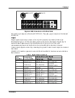
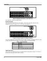
Figure 8. XLR Connectors on the Rear Panel
The audio
input
connector is Switchcraft E3FST-AU. The audio
output
connector is Switchcraft
E3MST-AU.
Digital
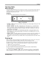
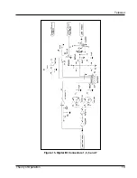
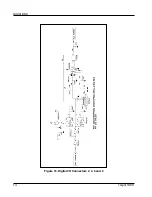
Digital signal connections are made via the 9-pin D connectors described in Table 4 and
illustrated in Figure 9. A 110
W
terminating resistor placed across the balanced inputs may be
needed if cable lengths using 110
W
twisted pairs are in excess of 6 feet. The serial
communications protocol can be RS-232 at one end and RS-422 at the other, if desired.
Contact closure input is activated by connecting it to ground. Contact closure output is an isolated
dry contact.
If SONY CCU interface operation is selected, RS-422 and RS-232 functions are not available at
that connector.
Table 4. Digital Cable Connections
Pin
Number
Connectors
1, 3, 5, 7 (Left)
Connectors 2,4,6,8 (Right)
Serial Com.
CCU
1
RS-422 in (
-
)
RS-422 in (
-
)
No connection
2
Contact out
No connection
CCU I/O
Jumper to pin 6
3
Ground
Ground
Ground
4
RS-232 out
RS-232 out
No connection
5
RS-422 out (
-
)
RS-422 out (
-
)
Jumper to pin 8
6
RS-422 in (+)
RS-232 in
RS-422 in (+)
RS-232 in
CCU I/O
Jumper to pin 2
7
Contact out
No connection
No connection
8
Contact in
No connection
Jumper to pin 5
9
RS-422 out (+)
RS-422 out (+)
No connection
2AMP, SLO BLO
DC INPUT
12-24VDC
OPTICAL I/O
A (Tx)
B (Rx)
DATA I/O
2
3
1
Male XLR
1
3
2
Female XLR
AUDIO IN 1
AUDIO OUT 1
AUDIO IN 2
AUDIO OUT 2
AUDIO IN 3
AUDIO OUT 3
AUDIO IN 4
AUDIO OUT 4
AUDIO IN 5
AUDIO OUT 5
AUDIO IN 6
AUDIO OUT 6
AUDIO IN 7
AUDIO OUT 7
AUDIO IN 8
AUDIO OUT 8
1
3
5
7
2
4
6
8


