Adder 882
8
1 April 1999
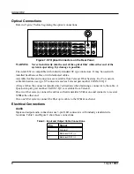
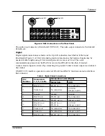
Figure 9. RS-422 D Connectors on the Rear Panel
The digital I/O connector is AMP 747905-2.
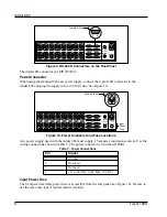
Power Connector
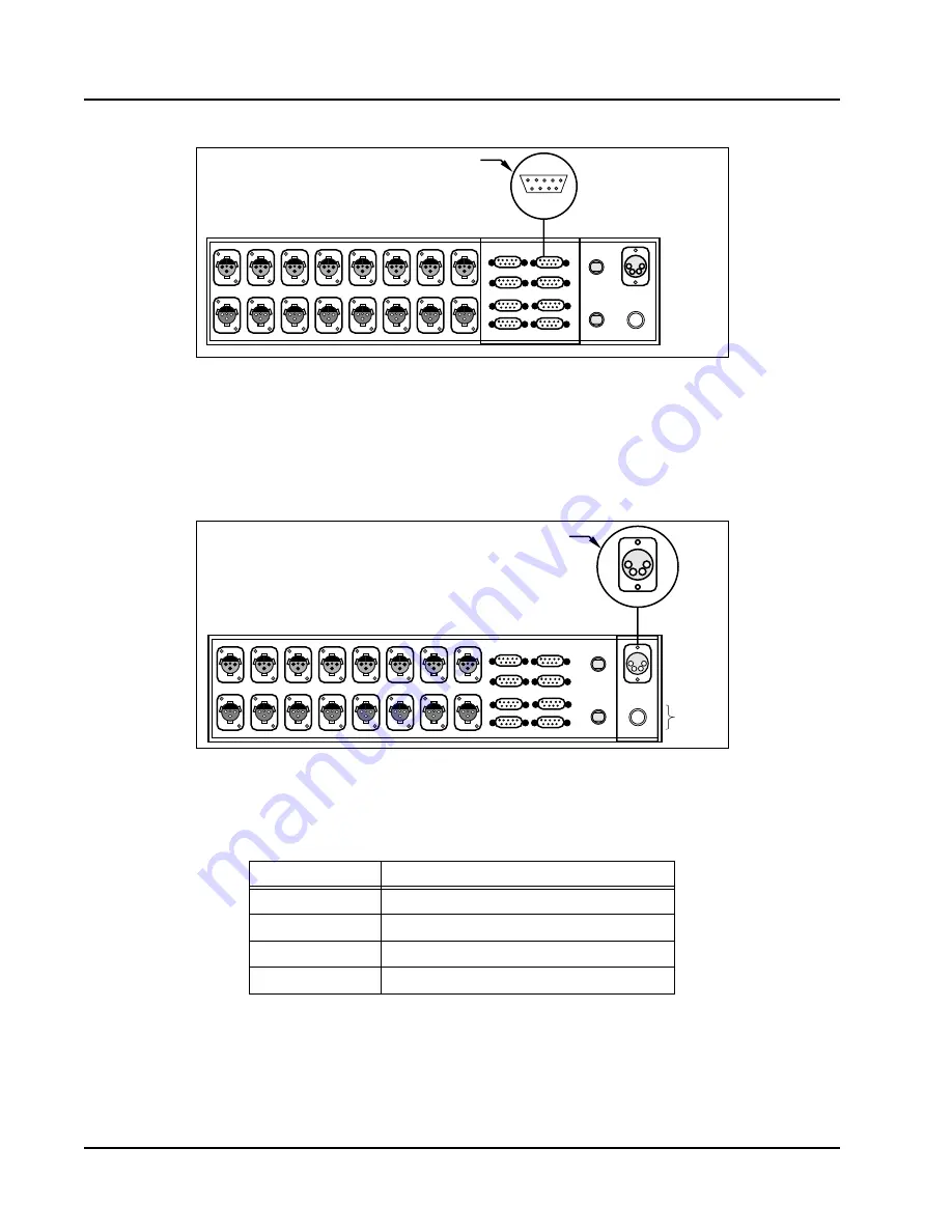
When using the standard Telecast power supply, connect the 4-pin XLR connector to the
Adder 882 and plug the supply into a 120 VAC line. See Figure 10.
Figure 10. Power Connector and Fuse Locations
Any power supply used with the Adder 882 must supply 1.5 amperes continuous current. Use the
wiring connections shown in Table 5. The power connector is Switchcraft D4M.
Input Power Fuse
The 2 ampere time delay power fuse is accessible from the rear panel (see Figure 10). Be sure to
use the same fuse type if replacement is required.
Table 5. Power Connections
Pin
Signal
1
Ground
2
Not used
3
Not used
4
+12 to 24 VDC (Abs. Max. 30 VDC)
2AMP, SLO BLO
DC INPUT
12-24VDC
OPTICAL I/O
A (TX)
B (RX)
DATA I/O
1
5
6
9
Female 9-Pin D
AUDIO IN 1
AUDIO OUT 1
AUDIO IN 2
AUDIO OUT 2
AUDIO IN 3
AUDIO OUT 3
AUDIO IN 4
AUDIO OUT 4
AUDIO IN 5
AUDIO OUT 5
AUDIO IN 6
AUDIO OUT 6
AUDIO IN 7
AUDIO OUT 7
AUDIO IN 8
AUDIO OUT 8
1
3
5
7
2
4
6
8
2AMP, SLO BLO
DC INPUT
12-24VDC
OPTICAL I/O
A (Tx)
B (Rx)
DATA I/O
Male 4-Pin XLR
1
2
3
4
AUDIO IN 1
AUDIO OUT 1
AUDIO IN 2
AUDIO OUT 2
AUDIO IN 3
AUDIO OUT 3
AUDIO IN 4
AUDIO OUT 4
AUDIO IN 5
AUDIO OUT 5
AUDIO IN 6
AUDIO OUT 6
AUDIO IN 7
AUDIO OUT 7
AUDIO IN 8
AUDIO OUT 8
Input
Power
Fuse
1
3
5
7
2
4
6
8


