background image

Telecast

 17

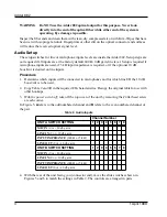
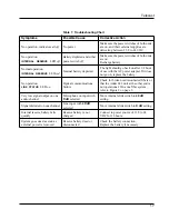
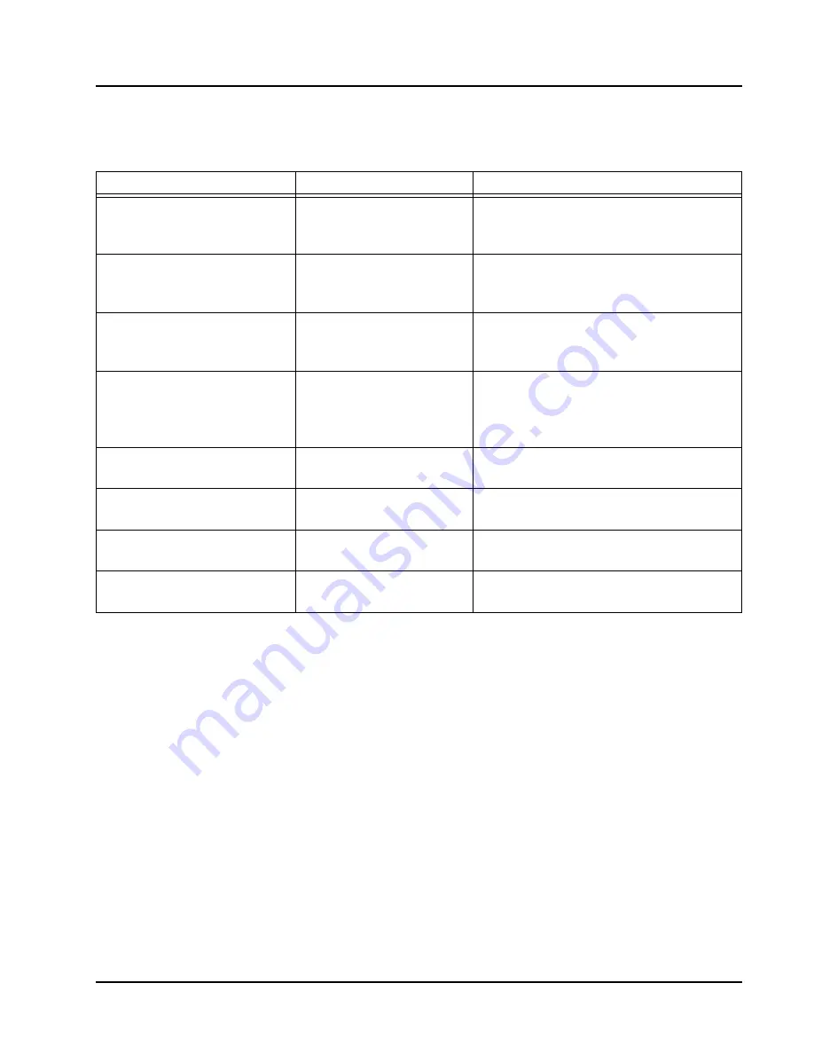
Table 7.  Troubleshooting Chart 

Symptoms

Possible Cause

Corrective Action

No operation, indicators all 

off

No power

Make sure the power switches of both units 
are 

on

, and their external supplies are 

delivering between 13.8 to 24 VDC.

No operation

INTERNAL


RESERVE


LED


off

Battery depleted and either 
power switch 

off

Make sure the power switches of both units 
are 

on

.

Recharge battery.

Normal operation

INTERNAL


RESERVE

 LED 

red

Internal battery depleted

The light should go back on after 1/2 hour 
of use with the AC power adapter. If it does 
not go on, replace the battery.

No operation

LINK


STATUS


LED 

on

Optical communications 
failure

Check for broken or disconnected Þbers or 
that the Adder 882 unit at the other end is 
not operational. On a one Þber system, 
refer to Figure 2 on page 2.

Very low signal output on one 
audio channel

Microphone on input with


dB


selected

Move internal slide switch to 

40 dB


setting.

Signal distorted on one channel

Line


input with 

4

dB 

selected

Move internal slide switch to 

dB

 setting.

Internal reserve battery fails 
quickly

Reserve battery is not 
charged

Connect to power source of 13.8 to 24 
VDC for 16 hours.

System goes dead as soon as 
external power is removed

Reserve battery dead or 
disconnected

Check the battery connection. 
Replace the battery if necessary.

Summary of Contents for Adder 882

Page 1: ...Adder 882 System Instruction Manual Telecast Fiber Systems Inc 102 Grove Street Worcester MA 01605 Tel 508 754 4858 Fax 508 752 1520 www telecast ber com...

Page 2: ...Adder 882 ii 1 April 1999...

Page 3: ...3 Fiber Optic Installation 3 Audio Setup 4 Procedure 4 Optical Connections 6 Electrical Connections 6 Input Power Fuse 8 Operating Details 9 Battery Charging 9 Powering Up 9 Theory of Operation 10 Di...

Page 4: ...Adder 882 iv 1 April 1999...

Page 5: ...ors on the Rear Panel 8 Figure 10 Power Connector and Fuse Locations 8 Figure 11 Front Panel 9 Figure 12 Electronics Block Diagram 10 Figure 13 Audio Input Buffer Circuit 11 Figure 14 Audio Output Buf...

Page 6: ...Adder 882 vi 1 April199...

Page 7: ...lable with several optical options and con gurations Standard connection with bidirectional signals carried on two optical bers at either 850 1300 or 1550 nm One ber connection with optically combined...

Page 8: ...WDM DET ST type Single Optical 850 nm 1300 nm LED WDM DET 8 Audio in 8 Digital in RS 422 8 Audio out 8 Digital out RS 422 Audio in 8 Digital in RS 422 8 Audio out 8 Digital out RS 422 8 connector Fibe...

Page 9: ...mage to the cables or their connectors Fiber Optic Installation The installer is responsible for providing the ber optic cable runs which are available from Telecast Fiber Systems Inc Refer to the Acc...

Page 10: ...desired on line inputs Procedure 1 Determine which inputs will be connected to microphones and for which line I O the 10 dB boost cut is to be used 2 Copy Table 2 and ll in the required I O characteri...

Page 11: ...Replace the top cover and gently reinstall the screws Figure 6 Main Circuit Board Zin Gain Lo Lo 40 10 40 10 Gain A B B A A B A B 10 10 Fine Level Switches are shown in the factory default position I...

Page 12: ...directions when fastening a connector to the cable A Quick crimp kit part number CKIT ST QC is available from Telecast On a two ber system connect the cables so that transmitter ST A at one end connec...

Page 13: ...ration is selected RS 422 and RS 232 functions are not available at that connector Table 4 Digital Cable Connections Pin Number Connectors 1 3 5 7 Left Connectors 2 4 6 8 Right Serial Com CCU 1 RS 422...

Page 14: ...ar panel see Figure 10 Be sure to use the same fuse type if replacement is required Table 5 Power Connections Pin Signal 1 Ground 2 Not used 3 Not used 4 12 to 24 VDC Abs Max 30 VDC 2AMP SLO BLO DC IN...

Page 15: ...EDs is on AUDIBLE ALARM An audible alarm has been incorporated into the Adder 882 in addition to the LED indicators on the front panel This alarm alerts the user that the internal batteries are discha...

Page 16: ...en inputs and outputs at opposite ends of the system Audio inputs and outputs are on separate sets of eight XLR connectors located on the rear panel Refer to Figure 1 on page 1 For details on setting...

Page 17: ...0 W balanced Figure 14 Audio Output Buffer Circuit 2 1 2 Ferrite Bead 8 3 1 8 4 MC33078 10pF 1 1 10pF 4 99k 8 5 2 49k 6 7 MC33078 680 3 1 2 1 0 2 Ferrite Bead 2 49k Audio In 1 2 3 6 5 4 Mode 4 99k 4 6...

Page 18: ...osure circuits are not provided on connectors 2 4 6 and 8 Refer to Table 4 Digital Cable Connections on page 7 for instructions on selecting the CCU capability When this option is selected the RS 422...

Page 19: ...Telecast Theory of Operation 13 Figure 15 Digital I O Connectors 1 3 5 and 7...

Page 20: ...Adder 882 14 1 April 1999 Figure 16 Digital I O Connectors 2 4 6 and 8...

Page 21: ...each audio channel Multiplexer Sequentially presents eight RS 422 digital inputs and eight digitized audio signals from the A D converters to the optical output driver and four to remote relay closure...

Page 22: ...power meter kit Cable repair kit Loop back cable to localize signals during installation test Replacement Ni Cad battery pack Quick crimp kit to attach ST connectors to ber optic cable Prefabricated c...

Page 23: ...go on replace the battery No operation LINK STATUS LED on Optical communications failure Check for broken or disconnected bers or that the Adder 882 unit at the other end is not operational On a one b...

Page 24: ...nto 600 Ws Unity gain 18 dBm peak 10 dB 8 dBm peak Frequency response 8 dBm from DC to 25 kHz 0 2 dB Output Signal Level 30 W balanced output into 600 Ws Unity gain 18 dBm peak 10 dB 8 dBm peak Freque...

Page 25: ...r shorted to circuit ground Remote contact closed Output Form 1A SPST NO isolated contacts Voltage 200 VDC Switched current 500 mA Carry current 1 2 A Contact resistance 200 mW Optical Characteristics...

Page 26: ...or inadequate maintenance and care Nor shall this warranty apply to any damage caused in whole or in part by attempts by personnel other than Telecast s personnel as approved in advance in accordance...

Reviews: