background image


Telecast

Introduction

 1


Introduction


The Telecast Adder


TM


882 System consists of two Adder 882 Þber optic 

multiplexer/demultiplexers that simultaneously send and receive up to eight audio signals, eight 
digital datas, and four remote relay closures  in each direction. These signals are transmitted on 
optical Þbers. Audio inputs are set up by internal DIP switches that set ampliÞer gain to accept 
either mic or


line levels. Audio outputs are always at line levels. Digital inputs and outputs are 

RS-422 and RS-232 compatible signals. Four of the digital connectors also provide contact 
closure input and output. The other four connectors alternatively provide SONY CCU compatible 
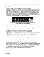
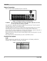
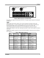
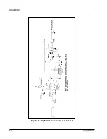
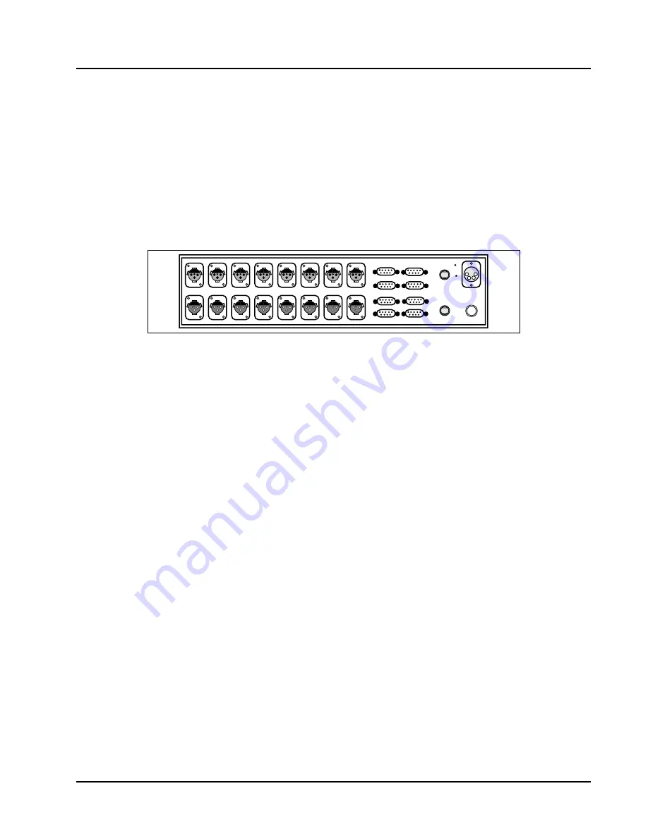
interfaces. All connections are made via the rear panel. See Figure 1.


Figure 1. Rear Panel of the Adder 882


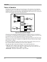
Within an Adder 882 unit, the audio signals are Þrst digitized and then multiplexed with the 
digital data and control signals. The combined electrical signal is converted to an optical signal, 
launched into the optical Þber and sent to a second Adder 882. This second unit receives the 
optical signal, converts it into an electrical data stream, demultiplexes the signals and restores the 
audio signals to analog levels.
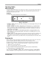
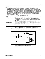
An internal Ni-Cad battery provides backup in the event of line power loss.
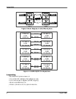
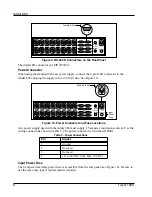
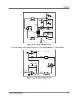
The Adder 882 is available with several optical options and conÞgurations.


¥ Standard connection with bidirectional signals carried on two optical Þbers at either 850, 1300, 

or 1550 nm.

¥ One Þber connection with optically combined bidirectional signals at 850/1300 nm or 

1300/1550 nm as shown in Figure 2.


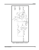
In a standard two Þber system, 


identical


 Adder 882 units are used at each location. The units both 

transmit at 850 nm on ST connector


A


and receive the 850 nm signal on ST connector 


B


. They are 

connected by the two Þbers so that the optical output of each box is connected to the optical input 
of the other. In both one and two Þber systems, the input of channel 1 on one unit becomes the 
output of channel 1 on the other unit, and vice versa.
In a one Þber system, the two Adder 882 units are 


not identical


 and are conÞgured before 

shipment. They must be used as a pair. The units are connected by a single Þber that is wavelength 
division multiplexed (WDM). One unit transmits from the


A


ST connector at a wavelength of 

1300 nm and also receives at 850 nm on the same connector. The other unit transmits from the 


A


ST connector at 850 nm and similarly receives at 1300 nm on the same connector.
Figure 3 illustrates available optical conÞgurations of the ADDER 882.

2AMP, SLO BLO

AUDIO IN 1

AUDIO OUT 1

DC INPUT
12-24VDC

OPTICAL I/O

 A(Tx) 

  B(Rx) 

DATA I/O

AUDIO IN 2

AUDIO OUT 2

AUDIO IN 3

AUDIO OUT 3

AUDIO IN 4

AUDIO OUT 4

AUDIO IN 5

AUDIO OUT 5

AUDIO IN 6

AUDIO OUT 6

AUDIO IN 7

AUDIO OUT 7

AUDIO IN 8

AUDIO OUT 8

1

3

5

7

2

4

6

8

Summary of Contents for Adder 882

Page 1: ...Adder 882 System Instruction Manual Telecast Fiber Systems Inc 102 Grove Street Worcester MA 01605 Tel 508 754 4858 Fax 508 752 1520 www telecast ber com...

Page 2: ...Adder 882 ii 1 April 1999...

Page 3: ...3 Fiber Optic Installation 3 Audio Setup 4 Procedure 4 Optical Connections 6 Electrical Connections 6 Input Power Fuse 8 Operating Details 9 Battery Charging 9 Powering Up 9 Theory of Operation 10 Di...

Page 4: ...Adder 882 iv 1 April 1999...

Page 5: ...ors on the Rear Panel 8 Figure 10 Power Connector and Fuse Locations 8 Figure 11 Front Panel 9 Figure 12 Electronics Block Diagram 10 Figure 13 Audio Input Buffer Circuit 11 Figure 14 Audio Output Buf...

Page 6: ...Adder 882 vi 1 April199...

Page 7: ...lable with several optical options and con gurations Standard connection with bidirectional signals carried on two optical bers at either 850 1300 or 1550 nm One ber connection with optically combined...

Page 8: ...WDM DET ST type Single Optical 850 nm 1300 nm LED WDM DET 8 Audio in 8 Digital in RS 422 8 Audio out 8 Digital out RS 422 Audio in 8 Digital in RS 422 8 Audio out 8 Digital out RS 422 8 connector Fibe...

Page 9: ...mage to the cables or their connectors Fiber Optic Installation The installer is responsible for providing the ber optic cable runs which are available from Telecast Fiber Systems Inc Refer to the Acc...

Page 10: ...desired on line inputs Procedure 1 Determine which inputs will be connected to microphones and for which line I O the 10 dB boost cut is to be used 2 Copy Table 2 and ll in the required I O characteri...

Page 11: ...Replace the top cover and gently reinstall the screws Figure 6 Main Circuit Board Zin Gain Lo Lo 40 10 40 10 Gain A B B A A B A B 10 10 Fine Level Switches are shown in the factory default position I...

Page 12: ...directions when fastening a connector to the cable A Quick crimp kit part number CKIT ST QC is available from Telecast On a two ber system connect the cables so that transmitter ST A at one end connec...

Page 13: ...ration is selected RS 422 and RS 232 functions are not available at that connector Table 4 Digital Cable Connections Pin Number Connectors 1 3 5 7 Left Connectors 2 4 6 8 Right Serial Com CCU 1 RS 422...

Page 14: ...ar panel see Figure 10 Be sure to use the same fuse type if replacement is required Table 5 Power Connections Pin Signal 1 Ground 2 Not used 3 Not used 4 12 to 24 VDC Abs Max 30 VDC 2AMP SLO BLO DC IN...

Page 15: ...EDs is on AUDIBLE ALARM An audible alarm has been incorporated into the Adder 882 in addition to the LED indicators on the front panel This alarm alerts the user that the internal batteries are discha...

Page 16: ...en inputs and outputs at opposite ends of the system Audio inputs and outputs are on separate sets of eight XLR connectors located on the rear panel Refer to Figure 1 on page 1 For details on setting...

Page 17: ...0 W balanced Figure 14 Audio Output Buffer Circuit 2 1 2 Ferrite Bead 8 3 1 8 4 MC33078 10pF 1 1 10pF 4 99k 8 5 2 49k 6 7 MC33078 680 3 1 2 1 0 2 Ferrite Bead 2 49k Audio In 1 2 3 6 5 4 Mode 4 99k 4 6...

Page 18: ...osure circuits are not provided on connectors 2 4 6 and 8 Refer to Table 4 Digital Cable Connections on page 7 for instructions on selecting the CCU capability When this option is selected the RS 422...

Page 19: ...Telecast Theory of Operation 13 Figure 15 Digital I O Connectors 1 3 5 and 7...

Page 20: ...Adder 882 14 1 April 1999 Figure 16 Digital I O Connectors 2 4 6 and 8...

Page 21: ...each audio channel Multiplexer Sequentially presents eight RS 422 digital inputs and eight digitized audio signals from the A D converters to the optical output driver and four to remote relay closure...

Page 22: ...power meter kit Cable repair kit Loop back cable to localize signals during installation test Replacement Ni Cad battery pack Quick crimp kit to attach ST connectors to ber optic cable Prefabricated c...

Page 23: ...go on replace the battery No operation LINK STATUS LED on Optical communications failure Check for broken or disconnected bers or that the Adder 882 unit at the other end is not operational On a one b...

Page 24: ...nto 600 Ws Unity gain 18 dBm peak 10 dB 8 dBm peak Frequency response 8 dBm from DC to 25 kHz 0 2 dB Output Signal Level 30 W balanced output into 600 Ws Unity gain 18 dBm peak 10 dB 8 dBm peak Freque...

Page 25: ...r shorted to circuit ground Remote contact closed Output Form 1A SPST NO isolated contacts Voltage 200 VDC Switched current 500 mA Carry current 1 2 A Contact resistance 200 mW Optical Characteristics...

Page 26: ...or inadequate maintenance and care Nor shall this warranty apply to any damage caused in whole or in part by attempts by personnel other than Telecast s personnel as approved in advance in accordance...

Reviews: