11
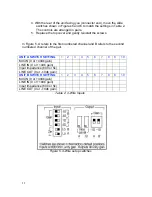
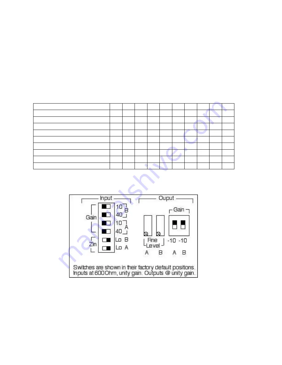
4. With the rear of the unit facing you (connector end), move the slide
switches shown in Figures 5 and 6 to match the settings in Table 2.
The controls are arranged in pairs.
5. Replace the top cover and gently reinstall the screws.
In Figure 5, A refers to the first numbered channel and B refers to the second
numbered channel of the pair.
UNIT A SWITCH SETTING
1
2
3
4
5
6
7
8
8
10
MIC IN (0 or +40db gain)
LINE IN (0 or +10db gain)
Input Impedance (600 or 5k)
LINE OUT (0 or –10db gain)
UNIT B SWITCH SETTING
1
2
3
4
5
6
7
8
8
10
MIC IN (0 or +40db gain)
LINE IN (0 or +10db gain)
Input Impedance (600 or 5k)
LINE OUT (0 or –10db gain)
Table 2: 4-Wire Inputs
Figure 5: 4-Wire setup switches


