11
Powering Up
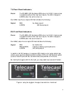
Power is applied to the units via the front panel on/off switch. The POWER LED
illuminates RED when 12-18VDC is present at either of the rear 4-pin power
inputs. This LED turns GREEN when the switch is moved to the ON position.
Standard Model Operation
For the standard (non-CWDM) Python II’s, each SDI channel BNC on the front
panel corresponds with an ST on the back panel. No electrical or optical
multiplexing is taking place and patching the fiber is simply a matter of matching
the fiber output on the transmitter to the proper fiber input on the receiver.
CWDM Model Operation
In CWDM equipped Python II’s, an internal course wavelength division
multiplexer combines multiple SDI channels optically onto a single fiber.
For example, in a P2-8TX-13CW-ST, 8 channels are optically muxed to a single
ST connector. All 8 signals are then sent to the receiver over one fiber where
they are de-muxed and presented on the front panel BNCs. On a 16-channel
unit, two ST connectors would be present on the rear panel.
There are no adjustments or patches for the user. All of the optical muxing is
accomplished inside the frame.
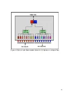
In the 16-channel unit with the band-splitter option, all 16 signals are carried on
one fiber. The first 8 channels are in the 1300nm optical window and the second
8 channels are in the 1550nm optical window. The band coupler combines the
aggregate output of each CWDM and couples that onto a single fiber. See Figure
8 on page 12.


