background image

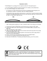
Important notice

Flat Sat Elegance is packaged in two separate cartons for transport reasons:

a)  the first package contains the driving unit with all the cables, and the Black Box;
b)  the second package only contains the dish.

•   It is important to check that the dish has not been damaged during transport when

the package is opened. In particular, check the following carefully:

•  By resting the dish edge against a flat surface (e.g. the floor or a wall) check that it makes

contact to the surface all around. If it is not so, try and make the edge level, without denting
the dish, or call our After-Sales Service.

•  After checking that everything is in order, install the dish on the driving unit as follows:

1)  Temporarily connect the Black Box to the Driving unit via the grey motor cable.
2)  Connect the Mir remote control expander to the "IR BLACK BOX" connector in the

Black Box.

3)  Power the Black Box using a battery.
4)  Press the System ON-OFF button on the remote control and wait (about 30 seconds)

for the dish support mast to rise.

5)  Once you have reached the desired position, disconnect the power supply cable to

switch off the Flat Sat Elegance.

6)  Secure the dish to the mast and screw down the four supplied screws.
7)  Turn the unit on again and wait for the antenna to close.
8)  Disconnect the Black Box, the battery and install the driving unit on the vehicle.

Recycling: 

with a view to reducing disposal of waste electrical and electronic

equipment as much as possible, do not throw out this appliance, once it has
reached the end of its life, together with other unsorted municipal waste, but make
use of a recycling centre.

YES


  NO

3

Summary of Contents for FlatSat Elegance

Page 1: ...UK Installation manual Flat Sat Elegance...

Page 2: ...Italy only 18 Connecting the Kit with a TNT SD M6000 receiver France only 19 Connecting the Kit with a TNT HD M5200 M7000 receiver France only 20 Configuration without Kit connection diagram 21 LNB r...

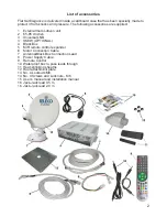
Page 3: ...85 cm dish 3 Universal LNB 3 SKEW OPTIONAL 4 Black Box 5 MIR remote control expander 6 Motor Connection Cable 7 Antenna Black Box Connection Lead 8 Power Supply Cable 9 Remote Control 10 Waterproof bo...

Page 4: ...nnect the Black Box to the Driving unit via the grey motor cable 2 Connect the Mir remote control expander to the IR BLACK BOX connector in the Black Box 3 Power the Black Box using a battery 4 Press...

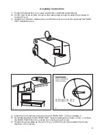
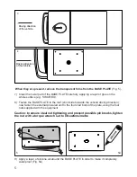
Page 5: ...owered OUTSIDE UNIT installation area 4 Clean the roof carefully in the area the OUTSIDE UNIT is to be installed in 5 Remembering that the OUTSIDE UNIT must be fastened as shown on Fig 3 remove the BA...

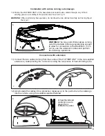
Page 6: ...cle driving direction now fasten the external powered unit to the four stud bolts of the plate using the four nuts supplied with the equipment Caution to ensure ideal nut tightening and prevent possib...

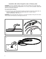
Page 7: ...ves according to the position as shown on Fig 6 WARNING When performing this operation do not draw the two cables forcefully as this might pull them out 6 Connection with extension 11 Connect the two...

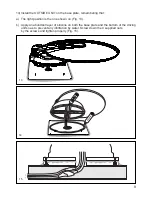
Page 8: ...ension cables and perform the following operations Connection with extension 13 Connect the Grey and White extension cables coming from inside the vehicle Fig 10 to the two cables of the outside unit...

Page 9: ...e right position is the one shown on Fig 13 b Apply an abundant layer of silicone on both the base plate and the bottom of the driving unit so as to prevent any infiltration by water Screw down the 4...

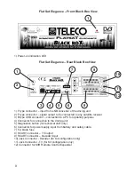
Page 10: ...connection to the driving unit 5 Diagnostics button for technical staff only 6 Connector for power supply input from battery and safety cable 7 5 A blade fuse 8 SCART connector TV output 9 SCART conne...

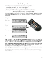
Page 11: ...battery compartment one on the Sat DECODER and one on the TV The Rec Type and the TV Type must be the same on all the 4 labels In the KIT with Black Box and Sat DECODER there are no 3 Kit labels one...

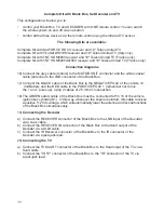
Page 12: ...to the NEGATIVE POLE of the vehicle 12 Volt Battery and the RED cable to the POSITIVE POLE remember not to mix the and poles up using 2 cables of 2 5 mm2 cross section 18 The GREEN safety cable of th...

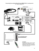
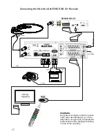
Page 13: ...rnator can give rise to equipment malfunction and or damage resulting in loss of the warranty 12 FORCE HD CI IR TV 19 TELECO United IR Receiver IR TV White Green Grey Not connected red black Connectin...

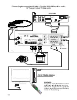
Page 14: ...leco United TV Italy only IR WARNING Any power connection made in points other than as indicated e g on the alternator can give rise to equipment malfunction and or damage resulting in loss of the war...

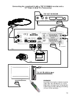
Page 15: ...g the complete Kit with a TNT SD M6000 receiver and a 19 Teleco United TV France only IR IR White Green Grey Not connected red black WARNING Any power connection made in points other than as indicated...

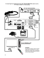
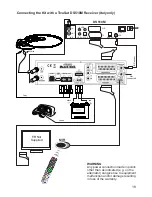
Page 16: ...the complete Kit with a TNT HD M5200 M7000 receiver and a 19 Teleco United TV France only IR IR White Green Grey Not connected red black WARNING Any power connection made in points other than as indi...

Page 17: ...ox to the NEGATIVE POLE of the vehicle 12 Volt Battery and the RED cable to the POSITIVE POLE remember not to mix the and poles up using 2 cables of 2 5 mm2 cross section 18 The GREEN safety cable of...

Page 18: ...HD CI MIR TV Not Supplied IR Receiver IR WARNING Any power connection made in points other than as indicated e g on the alternator can give rise to equipment malfunction and or damage resulting in lo...

Page 19: ...d 18 WARNING Any power connection made in points other than as indicated e g on the alternator can give rise to equipment malfunction and or damage resulting in loss of the warranty White Green Grey N...

Page 20: ...SD M 6000 ANT VCR SCART SPDIF TV SCART DC IN IR MIR TV Not Supplied IR WARNING Any power connection made in points other than as indicated e g on the alternator can give rise to equipment malfunction...

Page 21: ...200 M7000 LNB IN HDMI TV SCART IR DC IN AUDIO MIR TV Not Supplied IR WARNING Any power connection made in points other than as indicated e g on the alternator can give rise to equipment malfunction an...

Page 22: ...ted to Pin 15 of the vehicle ignition key cylinder D In this way whenever the engine is started this cable receives a positive 12 Vdc voltage which will automatically lower the antenna and lock all fu...

Page 23: ...remove the driving unit LNB rotation for ideal signal reception in extreme South western or South eastern areas in Europe Please be reminded that your outside low noise block converter LNB has its own...

Page 24: ...CELLANEA Power Supply 12Vdc 20 30 Absorbed current 5 A max Current in stand by 10 mA Fuse 5 A Dimensions 256 x 185 x 64 mm control box Weight Control Box 1 kg Flat Sat Elegance 65 external driving uni...

Page 25: ...24 Flat Sat Elegance 500...

Page 26: ...ase 13 10903 N 1 LNB right hand mast 14 10902 N 1 LNB left hand mast 15 10541 N 1 LNB mast right hand cable cover 16 10542 N 1 LNB mast left hand cable cover 19 06923 N 1 LNB Stark T1 20 10283 N 1 LNB...

Page 27: ...26 Flat Sat Elegance 650 850...

Page 28: ...ble cover 16 10542 N 1 LNB mast left hand cable cover 17 11010 N 1 Rubber support for LNB box top 18 10548 N 1 LNB box top 19 06923 N 1 LNB Stark T1 20 10283 N 1 LNB stop U bolt 21 10540 N 1 LNB tube...

Page 29: ...28...

Page 30: ...les HK1212 61 06371 N 8 Axial slew rings AS1226 62 06372 N 4 Needle cages AXK 1226 63 06785 N 4 Worm screw stop 64 03028 N 8 Screw M4x12 galvanized 65 03684 N 5 Self locking nut M6 UNI 7474 66 11081 N...

Page 31: ...N 4 Black rubber foot 5 12341 N 1 T0215 board Pos Code Q t Description 6 09705 N 1 5A Fuse 7 01458 N 8 Support 8 07798 N 1 PATCH UTP Cable 9 09318 N 1 Power supply cable 10 13520 N 1 T0331 board 11 1...

Page 32: ...7 06900 N 1 Gasket O SEALING VITON PG21 8 06901 N 1 SKINTOP cable gland PG21 9 06898 N 1 SKINTOP plastic nut PG21 11 07883 N 1 9 m coax cable F F connector 11 08998 N 1 2 m coax cable F F connector 11...

Page 33: ...32...

Page 34: ...ate conform to the following norms EN 60065 2002 EN 55013 2001 A1 2003 EN 61000 3 2 2000 A2 2500 EN 61000 3 3 1995 A1 2001 A2 2005 EN 55020 2002 A2 2005 according to the terms of the European directiv...

Page 35: ...34 Kit labels Black Box Decoder Sat TV 28 05 2013...

Page 36: ......

Reviews: