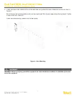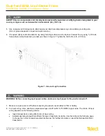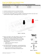
Dual-Feed 600A Load Center Frame
600CB10 & 600CB12 Installation Guide
16
© Telect, Inc. All rights reserved. 7.14.17 136429-2
509.926.6000 :: www.telect.com
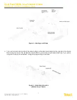
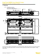
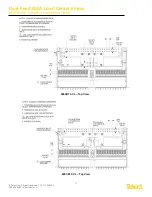
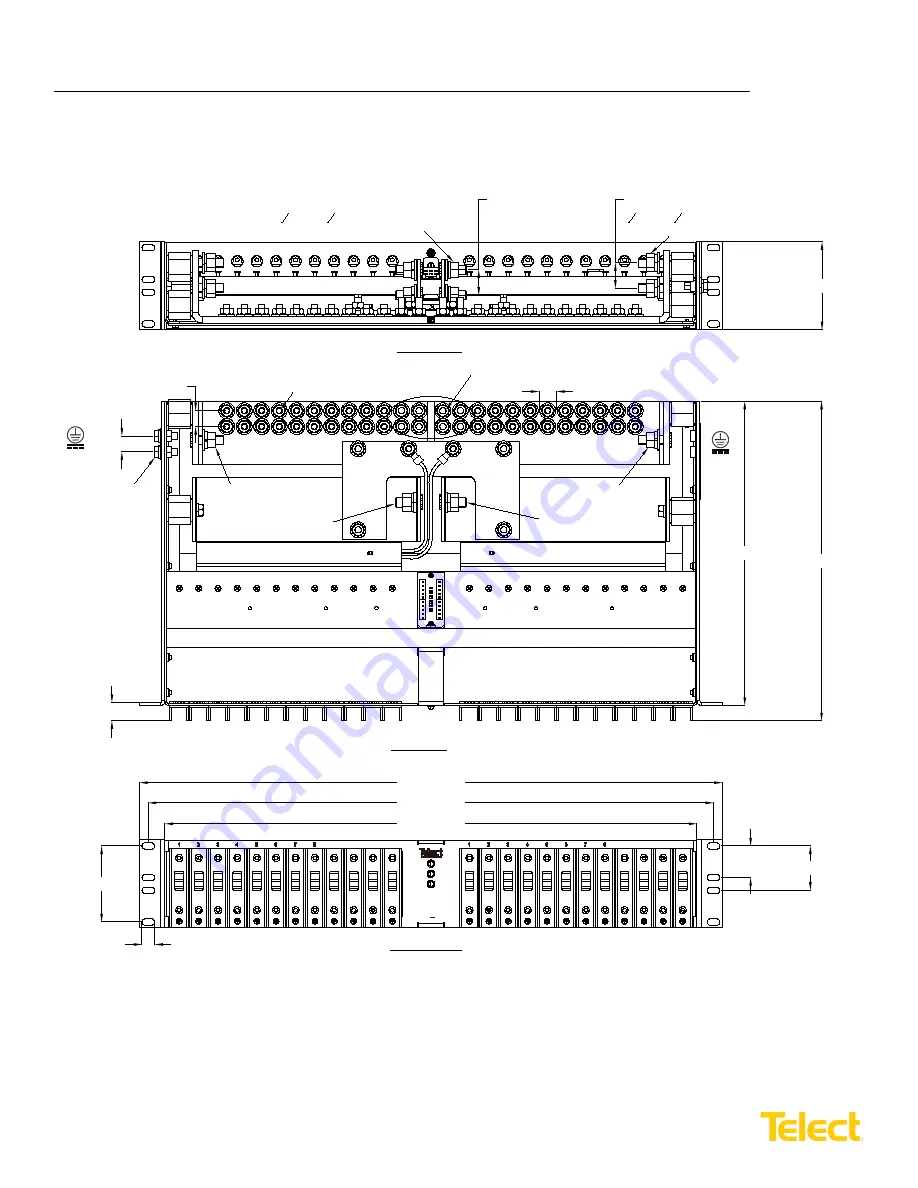
1.7 Drawings
Telect assumes no liability for the application or use of these products. Neither does Telect convey any license under its
patent rights or the patent rights of others. This document and the products described herein are subject to change
without notice.
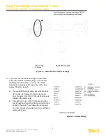
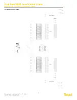
A
INPUT
BUS
600A
48
24
-
+-
B
V- - -
BAY
ALM
A PWR/
ALM
B PWR/
ALM
9
10
12
11
9
10
12
11
100A MAX PER POLE
23.00 [584.2]
22.31 [566.7]
21.00 [533.4]
1.25 [31.8] 1.75 [44.5]
3.00 [76.2]
0.50 [12.7]
FRONT VIEW
TOP VIEW
12.61 [320.3]
0.73 [18.5]
0.625 [15.9]
¼-20 x ¾ in.
0.625 [15.9]
¼-20 x ¾ in. Stud, KEPS Nut, & Washer
¼-20 x 1 in. Stud, KEPS Nut, & Washer
1.00 [25.4]
1.00 [25.4]
3
8
-16 x 1
1
4
in. Stud, Nut,
Lock Washer, & Flat Washer
3
8
-16 x 1
1
4
in. Stud, Nut,
Lock Washer, & Flat Washer
REAR VIEW
(ROTATED)
12.00 [304.8]
RTN A BUS
RTN B BUS
BATT A BUS
BATT B BUS
RTN A Input Terminal
RTN B Input Terminal
BATT A Input Terminal
BATT B Input Terminal
NOTES
1. Dimensions are in in. [mm].
2. Breakers/Fuses sold separately.
3. Breaker/Fuse line straps sold separately.
4. Max lug width for input BATT and RTN is ~50 mm (~2 in.)
0.69 [17.5], Max. Lug Width
(See Note 4.)
(See Note 4.)
3.47 [88.1]

