


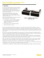


Dual-Feed 600A Load Center Frame
600CB10 & 600CB12 Installation Guide
II
© Telect, Inc. All rights reserved. 7.14.17 136429-2
509.926.6000 :: www.telect.com
Table of Contents
1.1 Overview ........................................................................................................................................................................... 1
1.2 Installation Guidelines ....................................................................................................................................................... 2
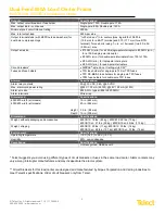
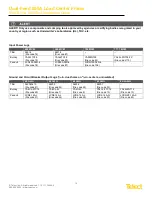
1.3 Specifications .................................................................................................................................................................... 2
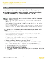
1.4 Installation Instructions ...................................................................................................................................................... 4
1.5 Parts & Accessories ........................................................................................................................................................ 13
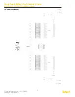
1.6 Interconnections .............................................................................................................................................................. 15
1.7 Drawings ......................................................................................................................................................................... 16
List of Figures
Figure 1 – 600CB10, 19" 10/10 Position Load Center Frame ................................................................................................ 1
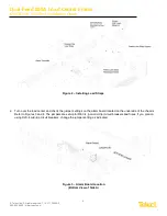
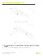
Figure 2 – Installing Load Straps ............................................................................................................................................ 5
Figure 3 – Alarm Board Location (Bottom View of Side A) ..................................................................................................... 5
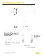
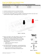
Figure 4 – Alarm Board Jumper Settings ................................................................................................................................ 6
Figure 5 – Alarm Wiring .......................................................................................................................................................... 6
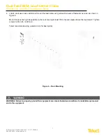
Figure 6 – Rack Mounting ....................................................................................................................................................... 7
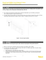
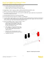
Figure 7 – Ground Lug Connection ......................................................................................................................................... 8
Figure 8 – Input Lugs .............................................................................................................................................................. 9
Figure 10 – Output Lug Connections .................................................................................................................................... 10
Figure 11 – Installing Circuit Breakers .................................................................................................................................. 11
Figure 12 – Installing Fuse Holders and Fuses .................................................................................................................... 11


