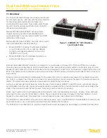
Dual-Feed 600A Load Center Frame
600CB10 & 600CB12 Installation Guide
2
© Telect, Inc. All rights reserved. 7.14.17 136429-2
509.926.6000 :: www.telect.com
1.2 Installation Guidelines
Elevated Operating Ambient
– If installed in a closed or multi-unit rack assembly, the operating ambient temperature of
the rack environment may be greater than the room ambient. Therefore, consideration should be given to installing the
equipment in an environment compatible with the maximum ambient temperature (TMA) specified by the manufacturer.
Reduced Air Flow
– Installation of the equipment in a rack should be such that the amount of air flow required for safe
operation of the equipment is not compromised.
Mechanical Loading
– Mounting of the equipment in the rack should be such that a hazardous condition is not achieved
due to uneven mechanical loading.
Circuit Overloading –
Consideration should be given to the connection of the equipment to the supply circuit and the
effect that overloading of the circuits might have on overcurrent protection and supply wiring. Appropriate consideration of
equipment nameplate ratings should be used when addressing this concern.
Reliable Earthing
– Reliable earthing of rack-mounted equipment should be maintained. Attention should be given to
supply connections other than direct connections to the branch circuit (e.g. use of power strips).
Disconnect Device
– A readily available disconnect device shall be incorporated in the building installation wiring.
1.3 Specifications
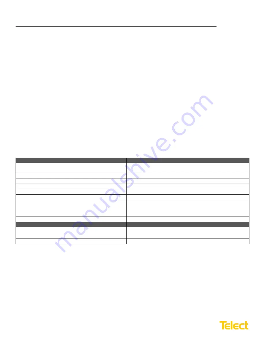
Inputs:
Specifications:
Voltage range (nominal voltage)
±
21.6V to
±
30V (nominal ±24 VDC)
-40V to -60V (nominal -48 VDC)
Max. input load rating
600A per side at max. operating ambient of 49
°
C (120
°
F)
Short circuit withstand rating
5000A
Nominal power loss at full load
Less than 75W per side @ 28,800W full load per side (600A x 48V)
Percentage of full power dissipation at nominal voltage
Less than 1%
Max. input interrupt device
750A
Input terminal studs (with nuts, flat washers and spring
washers) for dual-hole compression lugs
Two pairs of
3
/
8
-16 studs on 1-in. centers per terminal [max. lug
width of 1.94-in. (49.2 mm)] per pair. Torque nut (using
9
/
16
-in. or 15
mm wrench) to 150-in./lb. (~17 N
•
m), max.
Input wire size
#1 AWG to 750 MCM
Grounding:
Specifications:
Earth GND terminal bolts (with washers) for dual-hole
compression lug
Two pair of
1
/
4
-20 threaded holes on
5
/
8
-in. centers. Torque bolts
(using
7
/
16
-in. or 12 mm wrench) to 50-in./lb. (5.5 N
•
m), max.
Ground wire size
#2 AWG (min.) for any input interrupt device 400A or more


