background image

Dual-Feed 600A Load Center Frame 

600CB10 & 600CB12 Installation Guide 


© Telect, Inc. All rights reserved. 7.14.17 136429-2  
509.926.6000 :: www.telect.com 


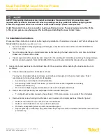
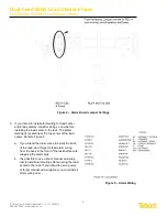
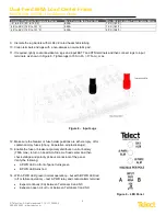
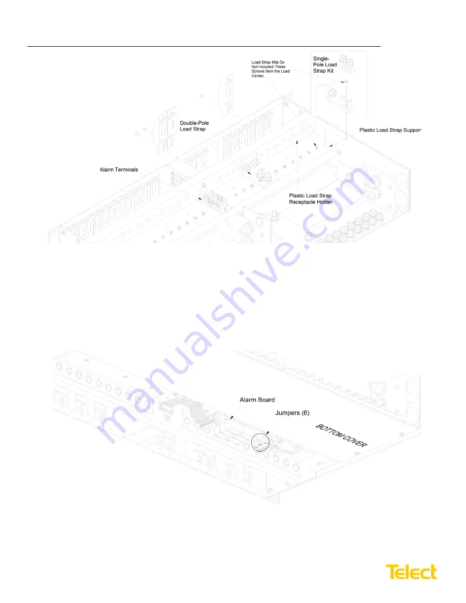
2.  Turn over the load center and check the jumper settings on the alarm board located on the underside of the chassis. 

Refer to Figures 3 and 4. The jumpers are set up for REC-4 (non-mid-trip) circuit breakers and fuses. If you plan on 
using RLS-4 mid-trip circuit breakers, change the jumper setting as indicated.  


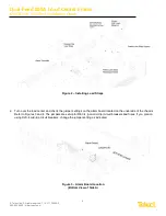
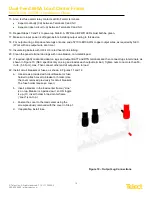
Figure 2 – Installing Load Straps 

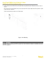
Figure 3 – Alarm Board Location 

(Bottom View of Side A) 

Summary of Contents for 600CB10

Page 1: ...Dual Feed 600A Load Center Frame 600CB10 600CB12 Installation Guide 600CB10 Front View 600CB10 C Rear View ...

Page 2: ... years Telect challenges the status quo and looks beyond what is possible in network connectivity and power management Founded in 1982 Telect is driven by the principles of innovation and customer service Headquartered in Liberty Lake WA the privately held company supports a global network of customers with a comprehensive product portfolio and a values driven corporate culture Our products and so...

Page 3: ...essories 13 1 6 Interconnections 15 1 7 Drawings 16 List of Figures Figure 1 600CB10 19 10 10 Position Load Center Frame 1 Figure 2 Installing Load Straps 5 Figure 3 Alarm Board Location Bottom View of Side A 5 Figure 4 Alarm Board Jumper Settings 6 Figure 5 Alarm Wiring 6 Figure 6 Rack Mounting 7 Figure 7 Ground Lug Connection 8 Figure 8 Input Lugs 9 Figure 10 Output Lug Connections 10 Figure 11 ...

Page 4: ...an be up to 200A The triple pole circuit breakers have a maximum load of 250A and the quad pole circuit breakers have a maximum load of 400A Sides A and B are electrically isolated except for the alarm card which contains power fuse and bay status relays with dry Form C contacts The contacts are connected to wire wrap pins to switch on external power to visual audio external alarms The alarm card ...

Page 5: ...s concern Reliable Earthing Reliable earthing of rack mounted equipment should be maintained Attention should be given to supply connections other than direct connections to the branch circuit e g use of power strips Disconnect Device A readily available disconnect device shall be incorporated in the building installation wiring 1 3 Specifications Inputs Specifications Voltage range nominal voltag...

Page 6: ... DC BBE 3 fuse holders for single pole TPC fuses TPW fuse holders for double pole TPC fuses Alarms Specifications Alarm relay contacts 2A 30 VDC 0 6A 60 VDC Max alarm card power rating 24V 103 mA 2 47W 48V 128 mA 6 14W Alarm wire size 24 AWG typical 26 to 20 AWG Alarm terminals Wire wrap Dimensions Specifications 600CB10 width all models 600CB12 width all models Height Depth 19 in 483 mm 23 in 584...

Page 7: ...packing and compare it to the packing list Immediately report any shipping damage defects or missing parts to Telect at 509 926 6000 Keep all documentation that comes with your shipment 1 Assign interrupter positions and install load straps for those positions before installing the load center in a rack as follows a Choose interrupter positions for breakers or fuses You may mix interrupter ratings...

Page 8: ...center and check the jumper settings on the alarm board located on the underside of the chassis Refer to Figures 3 and 4 The jumpers are set up for REC 4 non mid trip circuit breakers and fuses If you plan on using RLS 4 mid trip circuit breakers change the jumper setting as indicated Figure 2 Installing Load Straps Figure 3 Alarm Board Location Bottom View of Side A ...

Page 9: ...located near the top center of the load center Refer to Figure 5 a If you intend the alarm wires to exit at the back of the rack don t forget to feed alarm wiring from the back to the front of the rack before wire wrapping the alarm pins b It is possible to use a short manual wire wrap tool to install alarm wiring after securing the load center to the rack If you intend to use a power or larger ma...

Page 10: ...at least two sets of fasteners per side as shown in Figure 6 Mount the panel as high as possible on the rack leaving at least 1RU of access space above the load center Tighten screws to 35 in lb 4 29 N m Telect recommends using a seismic rack for best rigidity WARNING Failure to properly ground this equipment can create hazardous conditions to installation personnel and to the equipment Figure 6 R...

Page 11: ...e lug using 1 4 20 bolts flat washers and split washers provided as shown in Figure 7 Tighten the bolt to 50 in lb 5 5 N m WARNING Before connecting input power cables make sure input power to the panel is turned off 7 Make sure input power is off before connecting the panel s input cables to PDU or battery 8 For input wiring crimp dual hole compression lugs onto 1 AWG to 750 MCM copper wires The ...

Page 12: ...nals and then connect lugs to input terminals as shown in Figure 8 Tighten lugs to 150 in lb 17 N m max 12 Make sure the breaker or fuse holder positions are either empty off or contain dummy fuses phony inoperative all plastic slugs 13 Enable the fuse or breaker at primary distribution unit or battery 750A max to turn on Feed A to Side A of load center and then check voltage and polarity at input...

Page 13: ...terminal and lugs with non abrasive non metallic pad 21 If required lightly coat antioxidant on lugs and output BATT and RTN terminals and then connect lugs to terminals as shown in Figure 10 NEC specifics only one lug and load at each output terminal Tighten nuts to no more than 50 in lb 5 6 N m max Then connect other end of output wire to load 22 Install circuit breakers or fuses as shown in Fig...

Page 14: ...6 6000 www telect com 23 With the output loads devices fed by this load center disabled re enable fuses or breakers at primary distribution unit or battery 24 If applicable switch circuit breakers ON and then check voltage and polarity at loads Figure 11 Installing Circuit Breakers Figure 12 Installing Fuse Holders and Fuses ...

Page 15: ...l remain green 26 Check the CB F alarm terminals For a load center with fuses or non mid trip circuit breakers expect the following An open circuit Ω between Terminals C and NC Continuity 0Ω between Terminals C and NO 27 For a load center with mid trip breakers expect the following Continuity 0Ω between Terminals C and NC An open circuit Ω between Terminals C and NO 28 Re install operable fuses or...

Page 16: ...r Multi pole Breakers Part Number 30A 116671 125A 2 pole 134634 40A 116672 150A 2 pole 134635 50A 116673 175A 2 pole 135921 60A 118160 200A 3 pole 134636 70A 118161 225A 3 pole 134637 80A 118162 250A 3 pole 134638 90A 118163 400A 4 pole 143962 100A 118159 Adapter2 1 C C 600CB08 RPK Panel Part Number 600A Dual feed 10 10 load center frame vertical inputs 600CB10 600A Dual feed 10 10 load center fra...

Page 17: ...322TC38 Die code 19 YA342TC38 Die code 20 YA392NT38 Die code 24 YA44L 2NT38 FX Die code L115 Panduit LCD400 38D 6 Die code 76 LCD500 38D 6 Die code 87 LCDN750 38D 6 Die code 106 Ground and Circuit Breaker Output Lugs 1 4 in dual holes on 5 8 in centers uninsulated 8 AWG 6 AWG 4 AWG 2 AWG 2 0 AWG T B 542040410 Die code 21 54205 Die code 24 54206 Die code 29 54207 Die code 33 Burndy YA8CL 2TC14 Die ...

Page 18: ...Dual Feed 600A Load Center Frame 600CB10 600CB12 Installation Guide 15 Telect Inc All rights reserved 7 14 17 136429 2 509 926 6000 www telect com 1 6 Interconnections ...

Page 19: ...E 23 00 584 2 22 31 566 7 21 00 533 4 1 25 31 8 1 75 44 5 3 00 76 2 0 50 12 7 FRONT VIEW TOP VIEW 12 61 320 3 0 73 18 5 0 625 15 9 20 x in 0 625 15 9 20 x in Stud KEPS Nut Washer 20 x 1 in Stud KEPS Nut Washer 1 00 25 4 1 00 25 4 3 8 16 x 1 1 4 in Stud Nut Lock Washer Flat Washer 3 8 16 x 1 1 4 in Stud Nut Lock Washer Flat Washer REAR VIEW ROTATED 12 00 304 8 RTN A BUS RTN B BUS BATT A BUS BATT B ...

Page 20: ...Dual Feed 600A Load Center Frame 600CB10 600CB12 Installation Guide 17 Telect Inc All rights reserved 7 14 17 136429 2 509 926 6000 www telect com 600CB12 CL Top View 600CB12 VL Top View ...

Reviews: