background image

MIX 56 User Manual

4  Software Operation

122188-10 A0

Telect, Inc.

4-23

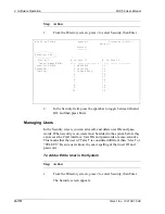
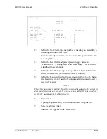
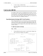
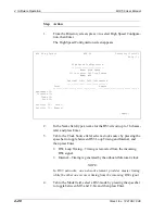
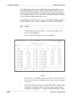
This illustration shows the E1 signal type (lines 22–28 unavailable):  

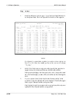
This illustration shows the E1 signal type (every fourth line unavailable):  

MIX 56 by Telect                   MIX 56                   Directory (CTRL+D) 

                            Low Speed Configuration                    Help (?) 
                            ----------------------- 

 Signal Type: E1 (lines 22-28 disabled) 

   Channel Number: 1                 Name: Low Speed 01 
      Type: E1                  InterFace: CI     LBO: Unavailable      [Apply] 

     State: Enabled                  Code: HDB3                     [Apply All] 

================================================================================ 
#  Name             Configuration Alrm    #  Name             Configuration Alrm 

-- ---------------- ------------- ----    -- ---------------- ------------- ---- 

 1 Low Speed 01     E1 C HDB3 Una Ena     15 Low Speed 15     E1 -- Disabled -- 
 2 Low Speed 02     E1 N AMI  Una Dis     16 Low Speed 16     E1 -- Disabled -- 

 3 Low Speed 03     E1 -- Disabled --     17 Low Speed 17     E1 -- Disabled -- 

 4 Low Speed 04     E1 -- Disabled --     18 Low Speed 18     E1 -- Disabled -- 
 5 Low Speed 05     E1 -- Disabled --     19 Low Speed 19     E1 -- Disabled -- 

 6 Low Speed 06     E1 -- Disabled --     20 Low Speed 20     E1 -- Disabled -- 

 7 Low Speed 07     E1 -- Disabled --     21 Low Speed 21     E1 -- Disabled -- 
 8 Low Speed 08     E1 -- Disabled --     22 ---------  Unavailable  ---------- 

 9 Low Speed 09     E1 -- Disabled --     23 ---------  Unavailable  ---------- 

10 Low Speed 10     E1 -- Disabled --     24 ---------  Unavailable  ---------- 
11 Low Speed 11     E1 -- Disabled --     25 ---------  Unavailable  ---------- 

12 Low Speed 12     E1 -- Disabled --     26 ---------  Unavailable  ---------- 

13 Low Speed 13     E1 -- Disabled --     27 ---------  Unavailable  ---------- 
14 Low Speed 14     E1 -- Disabled --     28 ---------  Unavailable  ---------- 


MIX 56 by Telect                   MIX 56                   Directory (CTRL+D) 

                            Low Speed Configuration                    Help (?) 

                            ----------------------- 
 Signal Type: E1 (every 4th line disabled) 

   Channel Number: 1                 Name: Low Speed 01        

      Type: E1                  InterFace: NI     LBO: Unavailable       [Apply] 
     State: Enabled No Alarms        Code: AMI                       [Apply All] 

================================================================================ 

#  Name             Configuration Alrm    #  Name             Configuration Alrm 
-- ---------------- ------------- ----    -- ---------------- ------------- ---- 

 1 Low Speed 01     E1 C HDB3 Una Ena     15 Low Speed 15     E1 -- Disabled -- 

 2 Low Speed 02     E1 N AMI  Una Dis     16 ---------  Unavailable  ---------- 
 3 Low Speed 03     E1 -- Disabled --     17 Low Speed 17     E1 -- Disabled -- 

 4 ---------  Unavailable  ----------     18 Low Speed 18     E1 -- Disabled -- 

 5 Low Speed 05     E1 -- Disabled --     19 Low Speed 19     E1 -- Disabled -- 
 6 Low Speed 06     E1 -- Disabled --     20 ---------  Unavailable  ---------- 

 7 Low Speed 07     E1 -- Disabled --     21 Low Speed 21     E1 -- Disabled -- 

 8 ---------  Unavailable  ----------     22 Low Speed 22     E1 -- Disabled -- 
 9 Low Speed 09     E1 -- Disabled --     23 Low Speed 23     E1 -- Disabled -- 

10 Low Speed 10     E1 -- Disabled --     24 ---------  Unavailable  ---------- 

11 Low Speed 11     E1 -- Disabled --     25 Low Speed 25     E1 -- Disabled -- 
12 ---------  Unavailable  ----------     26 Low Speed 26     E1 -- Disabled -- 

13 Low Speed 13     E1 -- Disabled --     27 Low Speed 27     E1 -- Disabled -- 

14 Low Speed 14     E1 -- Disabled --     28 ---------  Unavailable  ---------- 


Summary of Contents for MIX 56

Page 1: ... MIX 56 122188 10 A0 USER MANUAL ...

Page 2: ...efects in material and workmanship under normal use for two years after the original purchase by the end user The purchase date shall be assumed to be the latest of the following The date the product was shipped from Telect The date indicated on the returned warranty postcard provided that the postcard is returned within 90 days of the ship date or The date indicated on a photocopy of a sales rece...

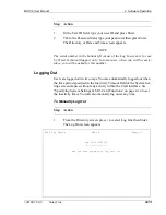
Page 3: ... its authorized employees and any agents or contractors using the Software in the performance of service for Licensee to use the Software solely in conjunction with the operation of the Product as specified in the Software documentation set forth in the Product user s manual b Neither the Software nor any part or portion thereof may be sublicensed copied reproduced or duplicated by any means or tr...

Page 4: ...e access to the Software only at Licensee s location Licensee further agrees that its contractors shall be deemed agents of Licensee and therefore Licensee shall have the same liability for its contractors as Licensee has for its employees and agents Licensee will promptly notify Telect of any unauthorized use of the Software Each party s obligations with respect to confidentiality shall survive t...

Page 5: ...ts rights or obligations or sublease sublicense or oth erwise transfer the Software without Telect s express prior written consent Severability If any of the provisions of this Agreement shall be invalid or unenforceable such invalidity or unen forceability shall not invalidate or render unenforceable the entire Agreement The entire Agreement shall be con strued as if not containing the particular...

Page 6: ...vi Telect Inc 122188 10 A0 ...

Page 7: ... Dimensions 1 11 Chassis Floor Weight Fully Loaded 1 12 Environmental 1 12 2 Installation Installation Considerations 2 1 Location and Space 2 2 Tools and Equipment 2 3 Power 2 4 Technical Support USA 2 4 Inspection 2 4 Installing MIX 56 2 5 Attaching the Mounting Brackets 2 5 Rack Mounting the Chassis 2 6 Cabling a System 2 8 Cross Connecting Circuits 2 12 Installing M13 Cards 2 13 Supplying Powe...

Page 8: ...he Craft Port 4 3 Craft Interface Basics 4 4 Navigating Between Screens 4 4 Navigating Within Screens 4 5 Adding and Selecting Field Information 4 5 Getting Help 4 5 Default Software Configuration 4 6 Security Screen 4 6 Save Configuration and Restore Configuration Screens 4 7 System Settings Screen 4 7 High Speed Configuration Screen 4 7 Low Speed Configuration Screen 4 8 Alarm Thresholds Screen ...

Page 9: ... BER Test 4 51 5 Owner Maintenance Replacing DSX Jack Tracer Lamps 5 2 Replacing DSX Jacks 5 3 Replacing M13 Cards 5 6 Replacing Alarm Cards 5 8 Updating the Software 5 9 TFTP Update 5 10 Craft Port Update 5 12 Transferring Software Versions Between Cards 5 14 6 Service In Case Of Difficulty 6 1 In Warranty Service 6 1 Out Of Warranty Service 6 1 Repacking For Shipment 6 2 Appendix A Connector Pin...

Page 10: ...x Telect Inc 122188 10 A0 ...

Page 11: ...S3 signal and separates a DS3 signal into 28 DS1 or 21 E1 signals Adding a second card provides 1 1 redundancy for all M13 functionality The 28 DS1 low speed channels and the DS3 high speed interfaces reside on one M13 card occupying one card slot while the protection card occu pies the second card slot The two cards are in constant communication and all configuration changes made to the active ca...

Page 12: ...itical major and minor external alarm contacts Remote provisioning and monitoring through SNMP or two concurrent Telnet sessions Separate alarm and event logs are rotating logs of up to 99 entries each Selectable alarm thresholds DS1 and DS3 loopback capabilities BER Testing DS3 signal format selectable between C bit or M13 mode C Bit Remote Control to the MIX 56 at the other end of the DS3 link D...

Page 13: ...off external alarms for a time period specified in the system settings screen of the Craft interface or through SNMP When pressed and held for three seconds it tests the LEDs on the LED panel and the M13 cards by chang ing the panel LEDs to yellow except Critical and Major which turn to red and changing the card LEDs to orange Testing the LEDs also resets the ACO timer DSX Jack 28 per system Used ...

Page 14: ...a mux Telect recommends using these DS1 wire wrap connections This method of connecting the low speed signals does not provide signal patching capabilities NOTE To use a system as a multiplexer with full DSX capabilities connect incom ing and outgoing DS1 signals to the front wire wrap pins LEDS The LED status indicators on the MIX 56 front panel are grouped into the following categories DSX Trace...

Page 15: ...cting condition Unlit No major alarms Minor Yellow One or more minor alarms Service processing and traffic unaffected Unlit No minor alarms Maintenance Yellow Diagnostic tests are being performed at least one circuit is out of service Unlit No diagnostic tests are being performed High Speed Red Receiving alarm indication signal AIS or experienc ing loss of signal LOS or out of frame OOF signal Yel...

Page 16: ...able management Chassis Ground One 10 32 dual ground stud per chassis Drain Wire Studs Two per system one for each 64 pin connector 6 32 ground stud for attaching cable drain wire DS1 In One per system 64 pin female connector for incoming low speed signals when using system as a DSX DS1 Out One per system 64 pin female connector for outgoing low speed signals when using system as a DSX DS3 In One ...

Page 17: ...ddresses in the System Interfaces screen See Specifying System Interface Settings on page 4 17 Power Receptacle One per system 20Vdc to 60Vdc Four position con nector 14 22 AWG used to supply redundant A B power to the system The power connector may be a wire clamping screw type terminal or a two piece mated connector Logic and Coaxial Shield Ground One per system Three position DIP switch Used to...

Page 18: ...R T R OUT IN 64 Pin Amp M13 Mux Low Speed High Speed DSX Without M13 DSX With M13 M13 With Amp Amp connector cabled to equipment Patch cord or wire wrap pins connect to another DSX panel Patch cord or wire wrap pins connect to another DSX panel Amp connector cabled to equipment Low speed signals are multiplexed into high speed Low speed signals are multiplexed into high speed This method of connec...

Page 19: ... 1 Descriptions 122188 10 A0 Telect Inc 1 9 DSX Jack Dimensions Schematic M O I 2 09 in 5 30 cm 1 58 in 4 00 cm 24 in 60 cm Wire Wrap Pins To M13 Backplane Mon SGND Jack Out In LED 1 R R 15 R n TL T R T1 R1 R1 n T n T1 n ...

Page 20: ...0 550 660 Long Haul DS1 selectable Cable Length 22 gauge ABAM or equivalent 6000 ft total cable length Line Build Out LBO 0 dB 7 5 dB 15 dB 22 5 dB These corre spond to approximate cable lengths of 6000 4500 ft 4500 3000 ft 3000 1500 ft and 1500 0 ft respectively Receive sensitivity down to 30 dB Far end equipment must have comparable long haul receive sensitivity E1 Impedance 120 ohms nominal bal...

Page 21: ...axial type cable Line Build Out LBO Adjusted automatically by system Power DC Input Voltage Range 20Vdc to 60Vdc DC Input Current 75 amp max at nominal 48Vdc per system 1 5 amp max at nominal 24Vdc per systems Wire Gauge 18 AWG recommended Fuse 1A for nominal 48Vdc 2A for nominal 24Vdc Alarm Contacts Form C Contact Ratings 400 mA at 125 Vac 750 mA at 30 Vdc Chassis Dimensions 5 20 in 13 21 cm 17 3...

Page 22: ...mental Operating Temperature 0 C to 50 C Nonoperating Temperature 40 C to 65 C Humidity 5 to 95 noncondensing Altitude 0 10 000 ft operating Shock Meets Telcordia GR 63 and NEBS level 3 requirements Vibration Meets Telcordia GR 63 and NEBS level 3 requirements Heat Dissipation 100 BTUs hour chassis with four M13 cards ...

Page 23: ...s técnicos autorizados ATTENTION Ce produit doit être installé et entretenu unique ment par des techniciens qualifiés ALERT ALERT These instructions presume you have verified that this Telect equipment being installed is compatible with the rest of the system including power ground circuit protection signal characteristics equipment from other vendors and local codes or ordinances ALERT ALERT MIX ...

Page 24: ...and the earthing conductor and also the point of earthing of the dc system The dc system shall not be earthed elsewhere z The dc supply source is to be located within the same pre mises as this equipment z Switching or disconnecting devices shall not be in the earthed circuit conductor between the dc source and the point of connection of the earthing electrode conductor The MIX 56 chassis mounts i...

Page 25: ...001 3002 for one or two panels respectively Tools and Equipment ALERT ALERT Only use crimping tools such as Burndy Y8MRB 1 or equivalent and components approved by agencies or certify ing bodies recognized in your country or region such as Un derwriter s Laboratories UL CSA or CE You need the following tools to install MIX 56 Flathead screwdrivers 3 16 to connect low speed cables 3 32 to wire powe...

Page 26: ...his equipment with a listed approved branch circuit breaker sufficiently rated to interrupt power at either 48 Vdc at 1 amp or 24Vdc at 2 amp The panel must be acces sible when operating the unit The chassis must receive 20Vdc to 60Vdc Since MIX 56 includes active components Telect recommends using a dual feed panel to provide input power redundancy Technical Support USA By e mail getinfo telect c...

Page 27: ...unting brackets you can set the chassis to project 3 4 or 5 inches from the front of the rack depending on which set of holes on the chassis you choose The following illustration shows the standard bracket being installed for 3 inch projection To allow more front projec tion use the middle set of holes for 4 inches or the last set of holes for 5 inches NOTE If you are mounting the chassis in a 23 ...

Page 28: ...sis requires 5 25 in of vertical space the height of the chassis When installing one chassis on top of another install a heat baffle of at least one rack unit above and below the pair See Location and Space on page 2 2 for an illustration NOTE Be sure the mounting brackets attached to the chassis are appropriate for the size of the rack See Attaching the Mounting Brackets on page 2 5 For 3 inch Pr...

Page 29: ...o the rack using the four 12 24 screws included 2 On one side of the chassis insert a wire management ring includ ed between the chassis mounting bracket and the head of the screw as shown below and tighten the screws tight enough to hold the ring in place 3 Repeat step 2 on the other side of the chassis ...

Page 30: ...ut route cables so as to create a mirror effect from the first system If using as a DSX only this requires using 64 pin connectors on the other system that are the reverse orientation of those used on the first system If you are using the system as a DSX only route the DS1 signals to the rear 64 pin connectors This method provides full DSX functionality including patching and monitoring using the ...

Page 31: ...a bles and two cable tie wraps To Cable a System as a DSX Step Action 1 Connect two 64 pin male cables to the two female connectors on the rear of the chassis marked DS1 In and DS1 Out 2 Tighten the two screws on each connector to secure the connectors to the chassis 3 Secure the cables to the chassis using tie wraps as shown here NOTE Prevent ground loops check the site s grounding practice stand...

Page 32: ...Vdc system and a 48Vdc system Industry standard tracer lamp circuits are designed to operate with a single system wide voltage NOTE If you prefer to connect the DS1 signals to the rear 64 pin connectors see To Cable a System as a DSX on page 2 9 This method of connecting the low speed signals does not provide signal patching capabilities 2 If your application requires changing the default Logic gr...

Page 33: ...uplex to match the MIX 56 Ethernet port 5 Connect external alarms to the Critical Major and Minor alarm contacts by pressing and holding the spring clip inserting the wire and then releasing the spring clip See the illustration on the next page Type of Ground Switch Position Definition Logic M13 Card Circuitry On Default Connected to chassis ground Off Not connected to chassis ground DS3 Coaxial S...

Page 34: ... DO NOT connect the tracer lamp TL signal between systems that operate on different supply voltages such as be tween a 24Vdc system and a 48Vdc system Industry standard tracer lamp circuits are designed to operate with a single system wide voltage Wire Wrap Cross Connect Color Scheme Connect from 1st termination wire color To 2nd termination wire color TL Green TL Green T Out Blue T Out Orange R O...

Page 35: ... the ESD jack when handling any MIX 56 components Step Action 1 Open the card door and loosen the two captive screws one per side holding the M13 card door in place Remove the door 2 Align the card with the card guides and gently insert it into the chassis by pressing the ejector handle against the card and pushing the card back See the illustration on the next page A B ...

Page 36: ...Supplying Power CAUTION CAUTION Do not supply power until all connections are made in accordance with requirements from local electrical codes Each system has its own power receptacle that accepts the included four position Phoenix type connector to supply redundant power to the system Telect recommends a minimum of 18 AWG wire and either a 1A fuse at nominal 48Vdc or a 2A fuse at nominal 24Vdc M1...

Page 37: ...same source as Side A to avoid triggering an alarm 4 If a mating connector is used insert the connector into the recepta cle and tighten the two screws until the connector is securely in place 5 Fuse the power source to supply power to the chassis INSTALLING THE OPTIONAL RJ CONNECTOR RETROFIT The optional RJ Connector Retrofit part 747 9999 2848 is a one piece unit that converts a system s wire wr...

Page 38: ...rap door by removing the four hinge screws shown below from the underside of the chassis 2 Uninstall the door s retainer clip by removing the two screws shown in the illustration on the next page NOTE If necessary insert the screwdriver through the access holes from beneath the chassis to remove the retainer clip screws OUT IN R R1 R1 R T T1 T1 T Receive Transmit Jack to Network Signal out of MIX ...

Page 39: ...ench tighten the mounting post until it is securely attached to the chassis 5 Repeat Steps 3 and 4 on the other side of the pin blocks 6 Gently place the holes on the back of the RJ Connector Retrofit over the wire wrap pins and carefully push the unit into place as Hinge Screws Retainer Clip Screws Retainer Clip Screw Access Holes Door Mounting Post Washer Mounting Post Hole Mounting Post Washer ...

Page 40: ...in it You may need to gently wiggle the unit as you push it into place 7 Insert the two included screws through the RJ Connector Retrofit and into the mounting posts as shown in the previous illustration and tighten them until the unit is securely in place as shown below Mounting Post Mounting Post Wire Wrap Pin ...

Page 41: ... See Chapter 4 Logging In 2 Access the System Interfaces screen and set the Modem Detect field to Enabled 3 Log out See Chapter 4 Logging Out 4 Set up the MIX 56 modem a Connect the modem serial port to the MIX 56 serial port with a null modem cable b Connect the modem to a phone line c Power up the modem 5 Press and hold the ACO switch until the LED test starts all LEDs light then release This ca...

Page 42: ...ng up at the remote modem 3 Disconnect the MIX 56 modem from the serial port 4 Connect the MIX 56 serial port to the local PC 5 Press and hold the ACO switch until the LED test starts then re lease This causes an LED test and resets the ACO as described on page 3 1 6 Login to the MIX 56 7 Access the System Interfaces screen and set the Modem Detect field to Disabled ...

Page 43: ...d the alarms are disabled for the length of time specified in the System Settings screen of the craft interface1 or through SNMP Testing LEDs and Resetting the ACO As part of the LED test the ACO is reset the alarms are enabled If the alarms are disabled when you test the LEDs you must disable them again see above when the test is complete to return them to their previous state 1 See Specifying Sy...

Page 44: ... connect ed to the front wire wrap pins you can perform all DSX functions includ ing cross connecting circuits with other network elements rerouting traffic with patch cords and nonintrusive monitoring signals NOTE If the system is used as a multiplexer but the DS1 signals are connected to the rear 64 pin connectors you cannot reroute traffic with patch cords Patching Signals ALERT ALERT When usin...

Page 45: ...ep Action 1 Insert a dual patch cord into the IN and OUT ports of the first jack module 2 Rotate the plug on the other end of the cord 180 degrees so that it is turned upside down from the first end and insert it into the IN and OUT ports of the second jack module Monitoring Signals You can perform nonintrusive signal monitoring by connecting your circuit monitoring device to the front monitor jac...

Page 46: ...ial port the modem detect code ATQ appears on the screen at the current location of the cursor when you release the ACO switch To clear the ATQ switch to another MIX 56 screen The modem automatically detects baud rate at the MIX 56 serial port when the modem is off line Once the modem is on line it will not change its baud rate If you change the MIX 56 baud rate System Interfaces screen while the ...

Page 47: ...face over RS232 serial connection TL1 Interface over RS232 serial connection Via Remote Control If the MIX 56 is connected over the DS3 link to another MIX 56 and they are both in C bit mode on the DS3 link then a remote control ses sion can be run where the user is controlling the MIX 56 at the remote end of the DS3 link Craft Interface over DS3 Link TL1 Interface over DS3 Link ALERT ALERT It is ...

Page 48: ... line system that can be accessed either by the Craft serial RS232 port or the Ethernet port The TL1 interface is covered in TL1 Design Telect document 126055 included with the MIX 56 System Software Ports Craft Port The Craft port is a nine pin DB9 RS 232 serial port located on the front of the chassis that connects to an RS 232 terminal or a PC running terminal emulation software in VT 100 mode ...

Page 49: ...lation software in VT 100 mode 2 Configure the terminal or PC port for 8 data bits 1 stop bit and no parity 3 Configure the terminal for the same baud rate as the MIX 56 is set for in the System Interfaces screen Choose between 9600 default 19200 38400 57600 or 115200 baud 4 Connect the DB9 male end of the included cable to the DB9 female port labeled Craft of the system 1 or 2 to which you are co...

Page 50: ...een appears 2 In the Select Screen field type the number of the screen you want to go to and press Enter The selected screen appears MIX 56 by Select MIX 56 Help Directory Select Screen __ Errors Access 11 High Speed Errors 15 min 1 Log Out 12 High Speed Errors 24 hr 2 Security 13 Low Speed Errors 15 min 14 Low Speed Errors 24 hr Save and Restore 15 Not Used Reserved 3 Save Configuration Alarms an...

Page 51: ...ges could affect service you must also tab to a button identified by surrounding brackets such as Apply At the button press Enter to apply the changes If you exit a screen on which you made changes without applying them you are prompted one last time to apply the changes The instructions in this chapter identify those fields which you toggle to get acceptable values and those in which you must typ...

Page 52: ...shown TELECT MIX 56 by Telect MIX 56 Technical Support 888 821 4856 509 921 6161 getinfo telect com High Speed Errors 15 min Help Press Esc to exit To View Errors in 15 Minute Totals To Clear the Current Span Totals 1 In the Time field type a time 1 Tab to the Clear button and in military time format press Enter Type the hour and press Enter then press Tab type the minutes 2 At the prompt type y a...

Page 53: ...Name Factory Field Default Setting System Name MIX 56 System Location Blank Contact Person Blank Date Varies Time Varies AIS Terminals LB Yes as per T1 403 Low Speed Type T1 LS Remote LB DIR DS3 Active Card Determined by system at power up Redundant M13 Cards Yes ACO Time 15 min Inactivity Timeout 15 min Loopback Permission No Reset Standby Card Control Local Telnet TL1 No Chassis and Card Version...

Page 54: ...ype T1 Interface NI Line Code B8ZS Line Build Out 0 110 ft State Disabled Field Default Setting sec AIS LOS RAI and OOF Alarm On 002 AIS LOS RAI and OOF Alarm Off 003 Low Speed ES 15 min Alarm On 065 Low Speed ES 24 hr Alarm On 648 Low Speed SES 15 min Alarm On 010 Low Speed SES 24 hr Alarm On 100 High Speed ES 15 min Alarm On 025 High Speed ES 24 hr Alarm On 250 High Speed SES 15 min Alarm On 004...

Page 55: ...s the first screen that appears1 and all screens are accessible to anyone There are three levels of security a user can be assigned Admin Rd Wr where the user has full access to the MIX 56 Config Test where the user has access to Screens 6 and 7 to Configure the DS3 and DS1 lines The user also has access to Screens 19 and 20 to conduct loopback and BER testing Read Only where the user can read all...

Page 56: ... can access the Craft interface User IDs and passwords are case sensitive This means that the user id Telect is considered different than telect or TELECT Be sure users know the exact spelling of their user ID and password To Add or Edit a User in the System Step Action 1 From the Directory screen press 2 to select Security then Enter The Security screen appears MIX 56 by Telect System 1 Directory...

Page 57: ...nique 5 Tab to the Password field and type a password from 6 to 16 charac ters Passwords do not need to be unique and are required to add a user to the system NOTE Check the password s spelling Once the password is added to the system it does not display on any screen If you have not spelled the password cor rectly the user may not be able to log in 6 Press Enter A prompt appears asking you to con...

Page 58: ... user A prompt appears asking you to confirm the deletion 4 Type y and press Enter The user s ID disappears from the selected slot Logging In When security is set to On you must log in to access the Craft interface and perform any functions You can only log in after your user ID and password have been added to the system in the Security screen see To Add or Edit a User in the System on page 4 10 N...

Page 59: ...ce you will be asked for this number Logging Out Users are logged out in two ways You are automatically logged out when the time period specified in the Inactivity Timeout field of the System Set tings screen elapses without any activity within the Craft interface See Specifying System Settings M13 Card Functions on page 4 14 to set the inactivity timer You can also manually log out at any time To...

Page 60: ...s include the date and time the active M13 card and times for the Alarm Cutoff and inactivity timer The System Settings screen also displays the system s chassis alarm card and software versions To Specify a System s Settings Step Action 1 From the Directory screen press 5 to select System Settings then Enter The System Settings screen appears MIX 56 by Telect MIX 56 Directory Ctrl D Help System S...

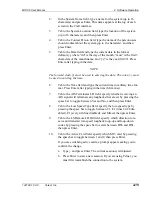
Page 61: ...e in military time for mat Press Enter after typing in the time hh mm ss 7 Tab to the AIS Terminates LB field specify whether receiving an AIS signal will terminate any loopbacks that are set by pressing the space bar to toggle between Yes and No and then press Enter 8 Tab to the Low Speed Type field specify the low speed type by pressing the space bar to toggle between T1 E1 lines 22 28 dis abled...

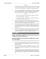
Page 62: ...imeout field type a number between 1 and 99 to specify the length of time in minutes without Craft interface ac tivity after which users will be logged out automatically and then press Enter 14 Tab to the Loopback Permission field specify whether to respond to requests for loopbacks from other equipment by pressing the spa cebar to toggle between Yes and No and then press Enter ALERT ALERT Resetti...

Page 63: ...rt you must connect to the local Craft inter face through the Craft port and set the system s IP Subnet Mask and Gate way addresses in the System Interfaces screen From the Directory screen type 9 to select System Interfaces and press En ter The System Interfaces screen appears To Change the Baud Rate Step Action 1 In the Baud Rate field press the spacebar to toggle between baud rates and then pre...

Page 64: ...me up to 16 characters which SNMP users will use for read privileges and then press Enter 2 Tab to the Write field and type a name up to 16 characters to which SNMP users will use for read privileges and then press En ter 3 Tab to the Trap field type a Trap name up to 16 characters which SNMP users will use to receive traps and then press Enter To Set SNMP Event Traps Tab to SNMP Event Traps press...

Page 65: ...Out The ping was sent but a response was not received within 5 seconds Occurs when the ping address cannot be found on the network Unable to Send Ping The ping could not be sent Occurs when the MIX 56 system s IP and Subnet Mask addresses have not been specified Configuring the High Speed Signal MIX 56 combines 28 DS1 or 21 E1 signals into a single industry standard DS3 signal and automatically ad...

Page 66: ...ss Enter DS3 Loop Timing Timing is recovered from the incoming DS3 signal Internal Timing is generated by the onboard Stratum 4 clock NOTE In DS3 networks one network element provides master timing while the other one recovers timing from the incoming DS3 signal 4 Tab to the Mode field select a DS3 mode by pressing the spacebar to toggle between M13 and C bit and then press Enter MIX 56 by Telect ...

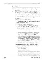
Page 67: ...Type y and press Enter Configuring the Low Speed Channels ALERT ALERT This procedure is service affecting In the System Configuration screen you can specify whether the system s DS1 signal type is T1 one of two types of E1 or mixed T1 s and E1 s When you select T1 all 28 channels become T1 and the Line Code choic es are limited to AMI or B8ZS The type of E1 signal you select determines the configu...

Page 68: ... 56 by Telect MIX 56 Directory CTRL D Low Speed Configuration Help Signal Type T1 Channel Number 1 Name Low Speed 01 Type T1 Interface CI LBO 000 110 ft Apply State Enabled Code B8ZS Apply All Name Configuration Alrm Name Configuration Alrm 1 Low Speed 01 T1 N B8ZS 110 Ena 15 Low Speed 15 T1 Disabled 2 Low Speed 02 T1 C AMI 220 Dis 16 Low Speed 16 T1 Disabled 3 Low Speed 03 T1 N B8ZS 330 Ena 17 Lo...

Page 69: ... E1 Disabled 24 Unavailable 11 Low Speed 11 E1 Disabled 25 Unavailable 12 Low Speed 12 E1 Disabled 26 Unavailable 13 Low Speed 13 E1 Disabled 27 Unavailable 14 Low Speed 14 E1 Disabled 28 Unavailable MIX 56 by Telect MIX 56 Directory CTRL D Low Speed Configuration Help Signal Type E1 every 4th line disabled Channel Number 1 Name Low Speed 01 Type E1 InterFace NI LBO Unavailable Apply State Enabled...

Page 70: ...RL D Low Speed Configuration Help Signal Type Mixed T1 s and E1 s Channel Number 1 Name Low Speed 01 Type E1 InterFace CI LBO Unavailable Apply State Enabled Code HDB3 Apply All Name Configuration Alrm Name Configuration Alrm 1 Low Speed 01 E1 C HDB3 Una Ena 15 Low Speed 15 T1 C B8ZS 22d Ena 2 Low Speed 02 E1 C AMI Una Ena 16 Low Speed 16 T1 C B8ZS 15d Ena 3 Low Speed 03 E1 N HDB3 Una Ena 17 Low S...

Page 71: ...ce for the NI and CI loop back codes The TI setting defines loop up and loop down codes that are different from the tra ditional NI and CI loop codes This causes the MIX 56 to not rec ognize the NI and CI loop codes when the interface is set to TI By not recognizing the NI and CI loop codes the MIX 56 just passes these loop codes through to the next piece of equipment The TI interface defines anot...

Page 72: ...ew configuration Saving a Configuration In the Save Configuration screen you can save up to three system configu rations in non volatile ram NVRam or you can save the entire NVRam configuration to a file A saved configuration in NVRam contains all the settings from the System Settings screen High Speed Configuration screen Low Speed Configura tion screen and Alarm Threshold screen The NVRam config...

Page 73: ... restore screen Screen 4 If you selected options 1 2 or 3 then a Tab to the Configuration Name field type a name for the configuration up to 16 characters and then press Enter A prompt appears asking you to confirm writing over the old configuration b Type y and press Enter The new configuration name ap pears beside the number you specified If you selected option 5 Save To a File then a A warning ...

Page 74: ... and TFTP Host IP Address fields must be filled out with a filename and the IP address of your TFTP server Screen 9 s IP Address and Subnet Mask fields must be filled out The filename entered on screen 10 is the base filename of the file saved here This file will have the base filename as specified on screen 10 with a filename extension of nvr Note this will overwrite any existing file with the sa...

Page 75: ...from a file or restoring to the Factory configuration resets the System Interfaces screen which includes the IP address Subnet Mask address and the Craft Port s baud rate This has the possibility of killing your communications link The Factory configuration does not have an IP address or Sub net Mask address If you restore this configuration remotely you will not be able to reconnect to the system...

Page 76: ...efault configu ration Type y and press Enter NOTES If the restored factory configuration has a different baud rate setting the Craft Port screen becomes unreadable To restore the screen change the baud rate to 9600 If the Craft connection is a telnet session this will kill your session The factory configuration clears out all the network addresses on the System Interfaces screen To restore a tel n...

Page 77: ...toring the NVRam from a file results in a reboot of the Mix56 card If you selected option 6 TFTP Restore From a File a A warning prompt appears read and understand the warn ing then press y and Enter The warning prompt is Restoring Configuration from a file This will result in a re boot of the active card causing a momentary traffic interruption on the DS3 DS1 lines The re boot will also cause thi...

Page 78: ...displayed for two time peri ods from Midnight the current day to the end of the last completed 15 minute period and from midnight the previous day to one second before Midnight of the current day Error Definitions These definitions are per ANSI T1 231 You can view all of the following DS3 errors in either of the displays described above Errored Seconds ES A second with one or more bipolar violatio...

Page 79: ...ll 96 periods at once Step Action 1 From the Directory screen type 11 to select High Speed Errors 15 min and press Enter The High Speed Errors 15 min screen appears 2 In the Time field type a time in military time format within the last 24 hours for which you want to view error counts Type hour and minute separated by a colon then press Enter If you enter an invalid time the display goes back to t...

Page 80: ...error counts you can clear both periods at once NOTE During the first 15 minute period of the day between 00 00 00 and 00 14 59 no error counts are shown in the 24 hour history screen Howev er you still can see error counts during this first 15 minute period by going to the High Speed Errors 15 min screen Step Action 1 From the Directory screen type 12 to select High Speed Errors 24 hr and press E...

Page 81: ... A second with one or more bipolar violations BPV excessive zeros EXZ or loss of signal LOS Errored Seconds Ratio ESR Ratio of Errored Seconds to total seconds Severely Errored Seconds SES A second in which 1544 or more BPVs EXZs or LOS occur Severely Errored Seconds Ratio SESR Ratio of Severely Errored Sec onds to total seconds Coding Violations CV A cumulative count of BPVs and or EXZs Loss of S...

Page 82: ...24 hours for which you want to view error counts Type the hour and minute separated by a colon and then press Enter If you MIX 56 by Telect system 2 Directory CTRL D Help Low Speed Errors 15 min Time 15 05 Channel 1 Clear Clear All Span 15 00 00 15 14 59 Name ES ESR SES SESR Name ES ESR SES SESR 1 Low Speed 3 0 005 1 0 001 15 Low Speed 0 0 000 0 0 000 2 Low Speed 0 0 000 0 0 000 16 Low Speed 0 0 0...

Page 83: ...king you to confirm the clear 5 Type y and press Enter The error counts clear To View Low Speed Errors in 24 Hour Histories The Low Speed Errors 24 hr screen updates every 15 minutes displaying error counts for two time periods from Midnight the current day to the end of the last completed 15 minute period Current View and from Midnight the previous day to one second before Midnight the current da...

Page 84: ...rtion of the screen is updated for the channel number you specified MIX 56 by Telect system 2 Directory CTRL D Help Low Speed Errors 24 hr Current View Current Channel 1 Clear Clear All Span 00 00 00 15 14 59 Name ES ESR SES SESR Name ES ESR SES SESR 1 Low Speed 3 0 005 1 0 001 15 Low Speed 0 0 000 0 0 000 2 Low Speed 0 0 000 0 0 000 16 Low Speed 0 0 000 0 0 000 3 Low Speed 0 0 000 0 0 000 17 Low ...

Page 85: ...to which you connected You must connect to the other system to manage its alarms and events When an alarm condition occurs within a system MIX 56 alerts you in the following ways The critical major or minor front panel LED lights The critical major or minor alarm contact on the rear panel activates sending the alarm to a separate alarm system An SNMP trap is sent if the network IP address Subnet M...

Page 86: ...rted de tails about the alarm the time remaining on the Alarm Cutoff ACO timer if it has been engaged and where you can engage and disengage the ACO Engaging the ACO closes the external alarm contacts turning them off while disengaging the ACO turns external alarms back on Critical Two or more low speed lines are in LOS DS3 receiving RAI DS3 LOS Major DS3 OOF DS3 receiving AIS DS3 SES and ES DS1 r...

Page 87: ... when an alarm is triggered and again when it is cleared Each page in the Alarm Log contains up to11 entries that show the date and time each alarm started or ended the type of alarm and a detailed explana tion of the alarm You can move forward or backward through the pages and when finished viewing alarms you can clear the entire log MIX 56 by Telect system 2 Directory Ctrl D Help Current Alarms ...

Page 88: ... you can set one threshold to trig ger the alarm and another to clear it ES and SES alarms do not need Alarm Off thresholds because they clear automatically when the time span on which they are based passes MIX 56 by Telect system 2 Directory Ctrl D Help Alarm Log Active Card Select Active Date Time Alarm Details 1 22 Oct 03 07 37 35 Mnr System multiple low speed failures on 2 22 Oct 03 07 37 35 C...

Page 89: ...ss of Signal or at least one Coding Violation CV occurs Errored Seconds 24 hours The number of ES in a 24 hour span Severely Errored Seconds 15 minutes The number of severely errored seconds SES in a 15 minute span A severely errored second is a second in which 320 or more CV occur Severely Errored Seconds 24 hours The number of SES in a 24 hour span Additionally you can set thresholds for the fol...

Page 90: ...utton only when redundancy switching is locked The Redundancy Switch Status field displays Normal if not locked or displays Locked Out if locked The Clear Lock but ton is only enabled if Status is Locked Out Viewing Events Any occurrence in the MIX 56 system whether initiated by a user or by the system is an event You can view events in the Event Log a screen that displays the last 99 events MIX 5...

Page 91: ...s Enter The Event Log clears NOTE If security is on then the user name will appear with the logged in mes sage This user name is coming from the security entry and if that entry on the security screen is deleted then there no longer is a user name to display with the logged in message The logged in message still exists there just isn t a user name to display with it MIX 56 by Telect system 2 Direc...

Page 92: ... MUX Decoder where it is looped back through the Encoder and put onto the DS3 stream The DS3 Received signal is looped back out as the DS3 Transmitted signal High Speed Local DS3 The signal is sent through the DS1 LIUs multi plexed and looped back before reaching the M13 MUX Encoder High Speed Line DS1 Ch xx in DS3 The signal path is the same as the Line DS3 loopback but instead of the entire DS3 ...

Page 93: ...emote loopback request is only available if the DS3 mode is set for C Bit NOTES The MIX 56 will respond to receiving low speed and high speed remote loopback requests if the Loopback Permission is set to Yes on the System Settings screen Low Speed Loop Up and Loop Down codes vary depending on the in terface setting and whether they are transmitted or received The inter face setting for the individ...

Page 94: ...S1 line The MIX 56 can be set up to either the DS3 or DS1 direction but not both at the same time The low speed remote loopback direction DS3 or DS1 is set by the LS Remote LB Dir field of the System Settings screen LS Remote LB Dir set for DS3 default The loop up and loop down codes are received and transmitted on the corresponding DS1 channel of the MUXed DS3 signal The loopback set on re ceivin...

Page 95: ...ing the loopbacks The Apply button is not enabled until a change in either the High Speed or Low Speed field is made MIX 56 by Telect Rt Mix56 Directory CTRL D Help Loopbacks LS Chan 1 Apply High Speed None Rx None Low Speed None Rx None Name DS3 DS1 Status Rx Name DS3 DS1 Status Rx 1 Low Speed 01 None None No 15 Low Speed 15 None Chan Disabled 2 Low Speed 02 None None No 16 Low Speed 16 None Chan...

Page 96: ...med This allows you to select either a C Bit DS3 test on the high speed line a T1 E1 test on a particular channel of the DS3 high speed line or an unframed pattern test on a specific low speed line The test pattern selections are dependant on which test mode is selected The test patterns available for the different modes are specified in the fol lowing table Mode Available Patterns C Bit DS3 Test ...

Page 97: ...ine is selected then you also specify which low speed channel to do the test on To Specify a BER Test Step Action 1 From the Directory screen press 20 to select BER Testing then press enter The BER Testing screen appears 2 In the Mode field select the mode by pressing the spacebar to tog gle between CBit DS3 Test on High Speed Line Unframed Test on Low Speed Line or T1 E1 Test on High Speed Line a...

Page 98: ...f the desired channel and then pressing enter NOTE This field is only available in the T1 E1 Test on High Speed Line or Unframed Test on Low Speed Line modes If the selected Low Speed Channel is disabled or unavailable then the Line Type display will change to either Line Disabled or Line Unavail 5 Tab to the Framed Signal field and toggle between yes and no by pressing the spacebar and then press...

Page 99: ...s zero in every channel Bit 2 0 and FS bit of frame 12 of the framed sig nal FS Bit NOTE This field is only available in the T1 E1 Test on High Speed Line mode 8 To apply the BER test selected tab to the Apply button and press enter A prompt will appear telling you that this action will cause a continuous traffic interruption and ask if you want to continue If a Low Speed Channel is selected that ...

Page 100: ...4 Software Operation MIX 56 User Manual 4 54 Telect Inc 122188 10 A0 ...

Page 101: ...rizados ATTENTION Ce produit doit être installé et entretenu unique ment par des techniciens qualifiés ALERT ALERT To avoid electrostatic discharge always wear a grounding strap plugged into the ESD jack when handling any MIX 56 components Telect s MIX 56 does not need preventive maintenance However you can replace or update the following components in the field DSX Jack Tracer Lamps PN 231422 1 D...

Page 102: ... with out breaking the pin as described below Step Action 1 Loosen the screw holding the LED panel faceplate in place 2 Carefully swing out the screw end of the faceplate just enough to allow the pin end to slip free from the enclosure 3 Set the faceplate aside 4 Pull the defective LED straight out with your fingers 5 Align the replacement LED with the LED socket in the jack mod ule as shown below...

Page 103: ...nel faceplate by inserting the pin into the enclo sure hole swinging the faceplate into position and inserting the captive screw into its slot so that the faceplate is flush with the chassis Tighten the screw REPLACING DSX JACKS To replace a DSX jack you must remove the LED panel faceplate which is held in place by a pin on one side and a screw on the other side You must pull the faceplate out at ...

Page 104: ... 122188 10 A0 3 Remove the faceplate as described on Page 5 2 4 Loosen the six screws holding the upper and lower jack retainers in place and remove the retainers as shown below Press down on the wire wrap door clip while removing the lower jack retainer ...

Page 105: ...u may need to wiggle the jack slightly to unseat it from the connectors 6 Insert the new jack into its slot and gently press it into place so that the jack connectors insert into the chassis connectors 7 Replace the upper and lower jack retainers and tighten the screws until the retainers are securely attached to the chassis 8 Re install the faceplate ...

Page 106: ... plugged into the ESD jack when handling any MIX 56 components ALERT ALERT Do not remove an M13 card that is carrying traffic Switch traffic to the Standby card by setting it as the Active card in the System Settings screen of the craft interface See Specifying System Settings M13 Card Functions on page 4 14 Step Action 1 Push up on the door and pull it off A B ...

Page 107: ...3 Align the new card with the card guides and gently insert it into the chassis by pressing the ejector handle against the card and pushing the card back 4 Again touching only the ejector handle firmly press the M13 card into place so that the connectors on the card fully mate with the connectors inside the chassis 5 Reattach the M13 card door M13 Card Ejector Handle ...

Page 108: ... remove the LED panel faceplate which is held in place by a pin on one side and a screw on the other side You must pull the faceplate out at an angle in order to remove it without break ing the pin as described below Step Action 1 Loosen the screw holding the LED panel faceplate in place 2 Carefully pull the end with the screw out slightly at an angle 3 Pull the faceplate to the side of the chassi...

Page 109: ...en them until the alarm card is se curely in place 8 Replace the LED panel faceplate by inserting the pin in the mount ing hole inserting the captive screw into its slot so that the face plate is flush with the chassis and tightening the screw UPDATING THE SOFTWARE The method you use to update a system s software depends on the configu ration of the system Redundant systems are updated using Trivi...

Page 110: ...opied prior to per forming any updates upgrades Performing updates upgrades on non re dundant M13 single card systems will cause loss of system configurations requiring configuration information to be re entered after any such update upgrade In addition performing updates upgrades on a redundant system may cause loss of system configurations If you have any questions please contact application eng...

Page 111: ...on and press Enter A prompt appears asking you to confirm updating the software NOTE If you get an error message saying TFTP update requires two cards it means your system does not have a standby card you need to use Serial Load as described in Updating Nonredun dant Systems 5 Type y and press Enter A message appears asking you to wait while the update loads The update loads to the standby card A ...

Page 112: ...ow the standby card to update to the new software from the former standby card now the active card When both cards have the same software version the minor alarm clears Craft Port Update Before beginning ensure the two update files internal flash and external flash are on the terminal or PC running terminal emulation software con nected to the MIX 56 system NOTE The Craft Port Update can be used o...

Page 113: ...s Raw ASCII or Text When the file finishes downloading the screen shows the Check sum of the file and asks if you want to continue Programming the External flash Please download the MIX56 external flash image file Downloading send the S Record or binary file Programming the External flash Please download the MIX56 external flash image file Downloading send the S Record or binary file downloading f...

Page 114: ...age appears stating the standby card s flash pro gram has been updated and you must now switch to the standby card to activate a flash update to the currently active card If your system is a redundant system continue as follows a As the warning message instructs press Esc to exit this screen The Update Flash screen reappears and the message Flash update successful appears on the Serial Port line b...

Page 115: ...arning screen appears asking you to confirm updating the standby card flash NOTE If you get an error message saying no standby card has been detect ed you cannot use this procedure you need to use Serial Load as described in Craft Port Update 3 Type y and press Enter The message Flash update in process please wait appears on the Transfer Program to Standby Card line When the process is com plete t...

Page 116: ...5 Owner Maintenance MIX 56 User Manual 5 16 Telect Inc 122188 10 A0 ...

Page 117: ...Representative 1 800 551 4567 1 509 926 6000 Telect will repair or replace defective products within the limits of the war ranty See Repacking for Shipment on the next page NOTE Call a Customer Service Representative for a Return Material Authoriza tion RMA before returning any equipment OUT OF WARRANTY SERVICE The procedure for out of warranty service is the same as for in warranty service except...

Page 118: ...G FOR SHIPMENT 1 Tag the equipment showing owner s name address and telephone number together with a detailed description of the problem 2 Use the original shipping container if possible If you do not have it package the equipment in a way to prevent shipping damage In clude the RMA inside the container and legibly print the RMA number on the outside of the package near the shipping address 3 Insu...

Page 119: ...X 7 RX Ring 15 DSX 15 RX Ring 23 DSX 23 RX Ring 31 Not Used 8 DSX 8 RX Ring 16 DSX 16 RX Ring 24 DSX 24 RX Ring 32 Chassis Ground Pin Signal Pin Signal Pin Signal Pin Signal 33 DSX 1 RX Tip 41 DSX 9 RX Tip 49 DSX 17 RX Tip 57 DSX 25 RX Tip 34 DSX 2 RX Tip 42 DSX 10 RX Tip 50 DSX 18 RX Tip 58 DSX 26 RX Tip 35 DSX 3 RX Tip 43 DSX 11 RX Tip 51 DSX 19 RX Tip 59 DSX 27 RX Tip 36 DSX 4 RX Tip 44 DSX 12 ...

Page 120: ... 7 DSX 7 TX Ring 23 DSX 23 TX Ring 39 DSX 7 TX Tip 55 DSX 23 TX Tip 8 DSX 8 TX Ring 24 DSX 24 TX Ring 40 DSX 8 TX Tip 56 DSX 24 TX Tip 9 DSX 9 TX Ring 25 DSX 25 TX Ring 41 DSX 9 TX Tip 57 DSX 25 TX Tip 10 DSX 10 TX Ring 26 DSX 26 TX Ring 42 DSX 10 TX Tip 58 DSX 26 TX Tip 11 DSX 11 TX Ring 27 DSX 27 TX Ring 43 DSX 11 TX Tip 59 DSX 27 TX Tip 12 DSX 12 TX Ring 28 DSX 28 TX Ring 44 DSX 12 TX Tip 60 DS...

Page 121: ... Closed Contact 2 MNR COM Minor Alarm Relay Common Contact 3 MNR NO Minor Alarm Relay Normally Open Contact 4 MJR NC Major Alarm Relay Normally Closed Contact 5 MJR COM Major Alarm Relay Common Contact 6 MJR NO Major Alarm Relay Normally Open Contact 7 CRT NC Critical Alarm Relay Normally Closed Contact 8 CRT COM Critical Alarm Relay Common Contact 9 CRT NO Critical Alarm Relay Normally Open Conta...

Page 122: ... A0 POWER CONNECTOR CRAFT PORT GROUND SWITCH Pin Signal 1 Not Used 2 TXD 3 RXD 4 Not Used 5 Ground 6 Not Used 7 CTS 8 RTS 9 Not Used B B A A 1 5 6 9 DS3 COAX SHIELD ON 1 2 3 LOGIC IN OUT ON Directly connected to chassis ground Default is all ON ...

Page 123: ......
Page 124: ...Telect Inc 1730 N Madson St P O Box 665 Liberty Lake WA 99019 509 926 6000 800 551 4567 Fax 509 926 8915 E mail getinfo telect com Internet http www telect com ...

Reviews: