Page 23
Telect, Inc. • USA +1.509.926.6000 • 52.33.3836.37.52
www.telect.com • © 2011 Telect, Inc., All Rights Reserved, 139249-1 A0
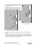
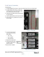
10. To install the covers, slip the bottom of the
side covers into the slot in the bottom
rail cover.
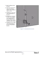
11. Screw in the remaining cover screws
and washers.
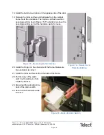
12. Use hole plugs to cover up the unused
grommet holes.
13. Install the wire connectors with a flat
side vertical.
This procedure is complete.
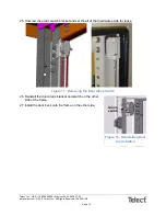
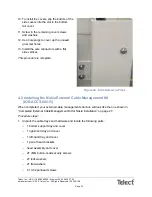
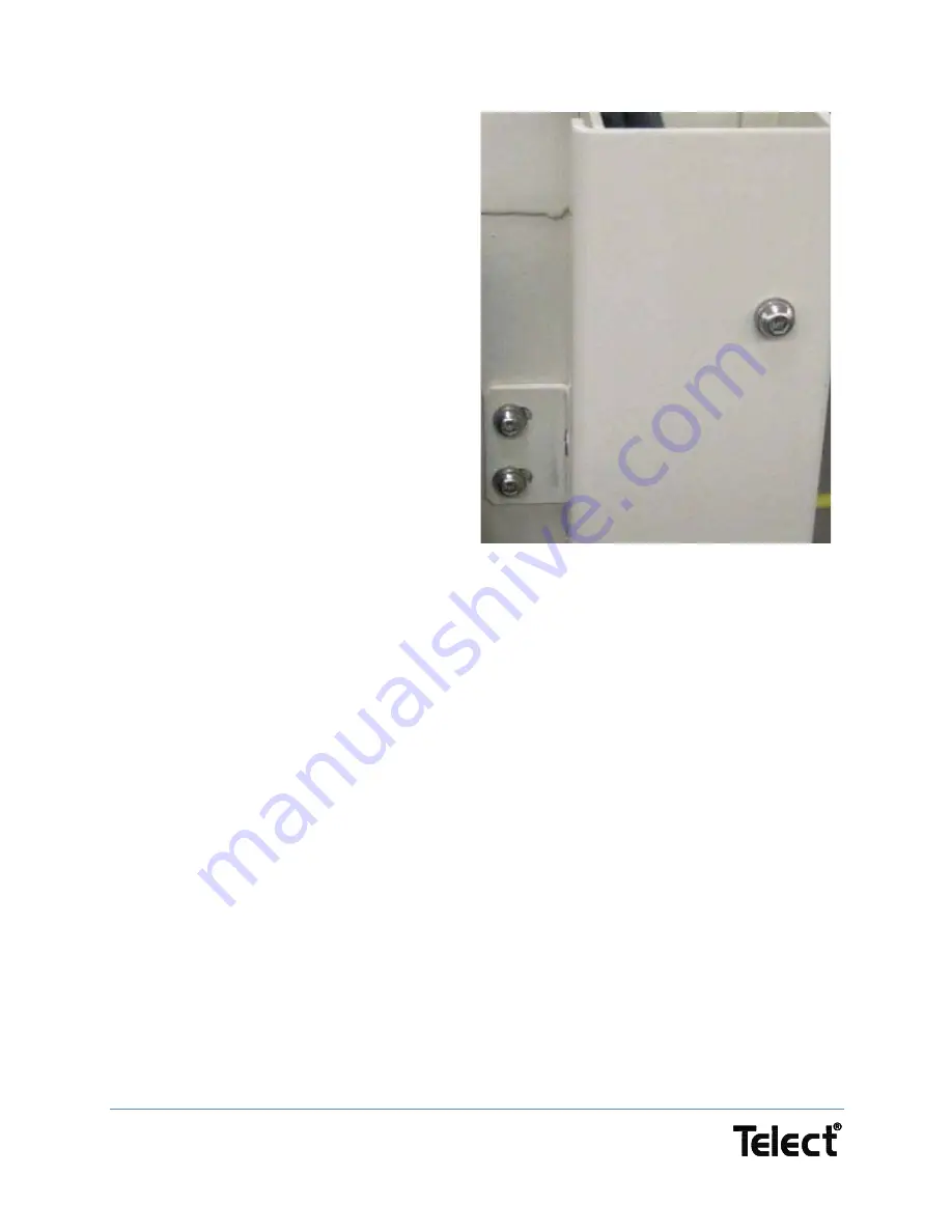
Figure 24 - Side Screws in Place
4.2 Installing the Nokia External Cable Management Kit
(IOE-ACCS-005-G)
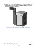
When completed, your external cable management structure will look like the one shown in
“Completed External Cable Management Kit for Nokia Installation” on page 27.
Procedure steps:
1. Unpack the cable trays and hardware and locate the following parts:
−
1 bottom support tray and cover
−
1 right-hand tray and cover
−
1 left-hand tray and cover
−
1 pair of head brackets
−
head assembly and cover
−
27 (M6) button-head security screws
−
27 lock washers
−
27 flat washers
−
6 10-32 panhead screws


