background image

Page 11

Telect, Inc. • USA +1.509.926.6000 • 52.33.3836.37.52
www.telect.com • © 2011 Telect, Inc., All Rights Reserved, 139249-1 A0

Chapter 3: Mounting Options for
the Enclosure

Use one of the following pad-mount procedures to mount your enclosure. Local operators 
provide platform mount details before installation. 

Whether you are mounting the enclosure directly to concrete, to a plinth, or mounting the 
enclosure/plinth combination directly to concrete, in most cases, you will need to install concrete 
anchors. Use the anchors appropriate to your needs. The following general installation 
instructions apply or you can use the anchor manufacturer’s installation instructions. Make sure 
you have the mounting kit that includes the isolation pad and hardware.

3.1 Installing the Enclosure using a 
Concrete Installation Kit  

Every enclosure ships with a Concrete Installation Kit, 
which contains 

an isolation pad

four M12 Seismic anchors

four each .030, .060, .120, .250 shims

four shoulder washers

four 2 x 2 x 1/44 (.812 hole) anchor plates

Procedure steps:

1. Install the anchors per normal industry standards.

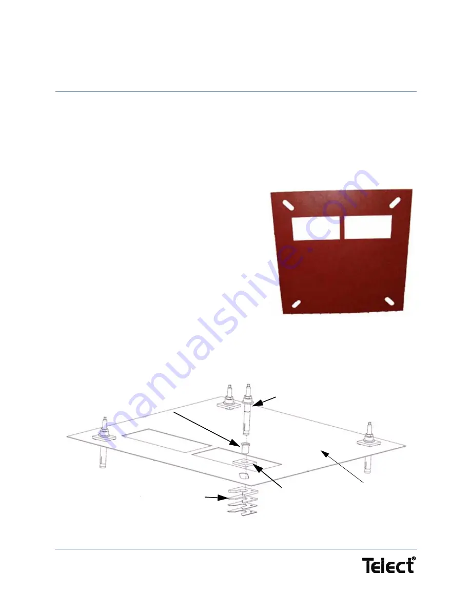
2. Place the isolation pad over the anchor bolts.

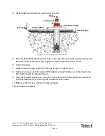
3. Check that the pad is level and doesn't rock on the slab. If it rocks, insert shims between the 

pad and the ground to eliminate any enclosure movement. See Figure 5.

Figure 4 - Isolation Pad

Isolation pad

Figure 5 - Isolation and Anchor Stack

Shims, as needed

M12 Seismic Anchor

Anchor Plate

Shoulder Washer


Summary of Contents for nrgSMART IOE-24S-A203

Page 1: ...nrgSMART 2 compartment 24RU Enclosures IOE 24S A203 Installation Guide ...

Page 2: ...ant and central office to inside the home Telect draws on more than 25 years of experience to deliver leading edge product and service solutions Telect is committed to providing superior customer service and is capable of meeting the dynamic demands of customer and industry requirements This commitment to customer and industry excellence has positioned Telect as a leading connectivity and power so...

Page 3: ...Tools 3 1 5 3 Recommended Tools 3 1 5 4 MDS Modules 3 1 6 Service 4 1 6 1 Technical Support 4 1 6 2 In Warranty Service 4 1 6 3 Out Of Warranty Service 4 1 6 4 Repacking for Shipment 4 1 7 Installation Flowchart 5 Chapter 2 Setting up the Enclosure 7 2 1 Transporting and Storing the Enclosure 7 2 2 Inspecting the Shipment 7 2 3 Unpacking and Preparing for Mounting 8 2 4 Maneuvering the Enclosure 9...

Page 4: ...ting DC Power Cables 44 8 3 Alarm and Control 46 8 3 1 Connecting Alarm and Control Wiring to the I O Board 48 8 3 2 Ground Strap and Radio Verification 49 Chapter 9 Turning up the DC Power System 51 9 1 Turning up the DC Power System 51 Chapter 10 Turning up the System 57 11 1 Alerts 57 11 2 Before You Turn on the System 60 11 3 Turning up the Enclosure 61 11 4 Cable Sizes 63 Chapter 11 Troublesh...

Page 5: ...om Cover 22 Figure 23 Bottom Rail Cover 22 Figure 24 Side Screws in Place 23 Figure 25 Attaching the Right Channel 24 Figure 26 Close up of Brackets 25 Figure 27 Left Side Installation 25 Figure 28 Brackets 26 Figure 29 Head 26 Figure 30 Completed External Cable Management Kit for Nokia Installation 27 Figure 31 Knockouts 30 Figure 32 AC Power Block 30 Figure 33 Lug Kit Part 305670 31 Figure 34 Gr...

Page 6: ... Figure 54 Connecting the Wiring into the RJ45 Connectors on the I O Board 50 Figure 55 Connecting the Wiring into the Terminal Blocks 50 Figure 56 Matching the Rectifier Slots with their Breakers 53 Figure 57 DC Power System 54 Figure 58 Rectifier Breakers Shown Turned OFF 54 Figure 59 Inserting the MDS Module 55 Figure 60 Inside of MDS Slot 55 Figure 61 Rear of MDS Module 55 Figure 62 Inserting ...

Page 7: ...sonal injury WARNING WARNING indicates a situation that could cause minor personal injury CAUTION CAUTION indicates a situation where the equipment could become damaged ALERT ALERT indicates a situation that could cause a problem with the operation of the machinery Telect Inc is not responsible for any equipment damage or poor operating performance when you do not follow these guidelines or when y...

Page 8: ...tall equipment you must adhere to the compartment s thermal load limits The estimated thermal budget associated with the installation of ancillary equipment in this enclosure is 100W MAX based on 38o C ambient and 40o C internal temperature Telect MUST review the actual equipment configuration to confirm the thermal acceptability of the equipment that you intend to install in this zone Consider yo...

Page 9: ...working at height if required 1 5 2 Essential Tools Standard electrical toolkit with insulated tools plus Standard and insulated hand tools Cable crimping tool and crimp lugs suitable for all cable sizes and connectors used Torque wrench with pivot head and insulated handle Heat shrink tubing and heat gun Digital multimeter Non static clothing 1 5 3 Recommended Tools Additional recommended tools i...

Page 10: ...at quality telect com Telect will ship a new replacement product along with a return shipping label and authorization information When you receive your replacement product pack up the defective product and return it to Telect using the return label box and any additional information provided 1 6 3 Out Of Warranty Service Follow the In Warranty directions above Telect charges a processing fee for o...

Page 11: ...igure 1 Installation Flowchart Installing the enclosure All materials present and in working order Yes No Notify carrier and Telect s service department Installing the batteries Transporting storing unpacking and inspecting the enclosure End Maneuvering the enclosure Mounting the enclosure Connecting the AC power Grounding the enclosure Connecting to Turning up the site other equipment Installing ...

Page 12: ...Page 6 Telect Inc USA 1 509 926 6000 Mexico 52 33 3836 37 52 www telect com 2011 Telect Inc All Rights Reserved 139249 1 A0 This page intentionally left blank ...

Page 13: ... calls or 509 921 6161 Option 2 or email us at getinfo telect com Inspect equipment after unpacking and compare it to the packing list Immediately report any shipping damage defects or missing parts to Telect at 1 800 551 4567 Keep all documentation that comes with your shipment Telect is not liable for shipping damage If the product is damaged notify the carrier and call Telect s Customer Service...

Page 14: ...ificate of Conformity Product SC200 00 McLean Warranty Card Yellow McLean Instruction Manual To find additional documents 1 Go to http www telect com www Support TechnicalAssistanceCenter aspx 2 At the Telect screen shown in Figure 2 go to Docs and configs on the left hand side 3 Find the finished goods part number you are looking for in the table that appears then find the link to the document yo...

Page 15: ...s for the enclosure as configured by Telect plus any additional customer installed auxiliary equipment before performing the lift A site installation engineer should verify that you have adequate support before you lift anything 2 4 Maneuvering the Enclosure Procedure steps 1 Attach lifting equipment to the eye bolts 2 Lift the enclosure with hoist system Make sure the straps are equal in length t...

Page 16: ...Page 10 Telect Inc USA 1 509 926 6000 Mexico 52 33 3836 37 52 www telect com 2011 Telect Inc All Rights Reserved 139249 1 A0 This page intentionally left blank ...

Page 17: ... anchor manufacturer s installation instructions Make sure you have the mounting kit that includes the isolation pad and hardware 3 1 Installing the Enclosure using a Concrete Installation Kit Every enclosure ships with a Concrete Installation Kit which contains an isolation pad four M12 Seismic anchors four each 030 060 120 250 shims four shoulder washers four 2 x 2 x 1 44 812 hole anchor plates ...

Page 18: ...ghten the studs 7 Install the anchor plates and then thread the torque nut onto the stud 8 Tighten the torque nut until it shears off the plastic encased holding nut At the shear point the holding nut will be properly torqued 9 Place the shoulder washer over the anchor and make sure it is firmly seated to prevent the mounting hardware from contacting the enclosure s sheet metal 10 Make sure that t...

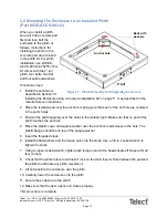
Page 19: ...he anchors are centered in the pad s holes 3 Position the plinth squarely over the holes in the isolation pad Make sure that no part of the plinth touches the anchors 4 Place the plastic cover and square washer over the anchor s metal sleeve in the hole The plastic flange should be on top of the square washer 5 Insert the threaded studs 6 Install the flat washers and the torque nuts onto the studs...

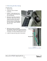
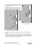
Page 20: ...he windstay bracket at the bottom inside corner of the en closure by using a 7 16 socket to remove the two 1 4 20 Keps nuts circled in Figure 8 and flatwashers from the bracket Set the hardware aside for reuse 5 Disconnect the door s ground wire from the frame Follow the ground wire to the frame connection point Use a 7 16 socket to remove the 1 4 20 keps nut Set the hardware aside for reuse 6 Loc...

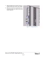
Page 21: ...2011 Telect Inc All Rights Reserved 139249 1 A0 7 While supporting the door lift the hinge pins upward until they click into the open position 8 Remove the door from the cabinet One per son should hold the door while the other pulls out the hinge pins Figure 10 Lifting Hinge Pin ...

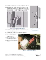
Page 22: ...ket wrench to remove the nuts Set the hardware aside for reuse 11 Remove the door handle using a 2 Phillips head screw driver Set the hardware aside for reuse 12 Remove the rod controller rods and rod guides Note the orientation of the assembly before you remove the hardware This will be helpful later when you reinstall the assembly Once you have removed the handle and the rod guide hardware as sh...

Page 23: ...g a 7 16 socket wrench Set the hardware aside for reuse 15 Reinstall the ground wire on the opposite side of the door 16 Reinstall the rod control ler rods and rod guides on the opposite side of the door Make sure the orientation of the control ler and the rods is correct 17 Reinstall the door handle on the opposite side of the door Finger tighten the bolt Figure 13 Removing Rod Controller ...

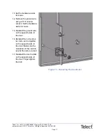
Page 24: ...own Figure 15 The bottom two have the openings pointing up Set the hardware aside for reuse Figure 15 Removing Roller Catches 20 Install the hinges on the other side of the frame Make sure the orientation is correct 21 Install the roller catches on the other side of the frame 22 Pull the body of the alarm switch out towards you from inside the bracket 23 Disconnect the wiring from the back of the ...

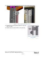
Page 25: ... 1 A0 25 Unscrew the alarm switch bracket and set the all of that hardware aside for reuse Figure 17 Removing the Door Alarm Switch 26 Reinstall the door alarm bracket and switch on the other side of the frame 27 Install the door back onto the frame on the other side Alarm switch Figure 18 Reinstalling Door Alarm Switch ...

Page 26: ...r and middle hinge pins downwards and the lower hinge pin upwards until they click into place 29 Reconnect the ground wire 30 Reinstall the windstay bracket on the other side of the frame 31 Connect wires disconnected in steps 2 and 3 to the door This procedure is complete Figure 19 Pushing Hinge Pins Figure 20 Reinstalling Windstay Bracket ...

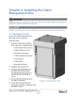
Page 27: ...agement Kit IOE ACCS 006 G Procedure steps 1 Unpack the cable trays and hard ware and locate the following parts 1 bottom support tray and cover 1 right hand tray and cover 1 left hand tray and cover 17 button head security screws 17 lock washers 17 flat washers 4 liquid tight cord grips 2 Install the side channels first 3 Using the provided hardware fin ger tighten the security screws with their ...

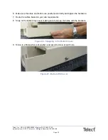
Page 28: ...he sides and bottom are positioned correctly and tighten the hardware 7 Route the cables based on your site requirements 8 Snap on the bottom tray cover making sure to line up the holes with the brackets Figure 22 Snapping in the Bottom Cover 9 Screw in a flat washer lock washer and security screw at each hole Figure 23 Bottom Rail Cover ...

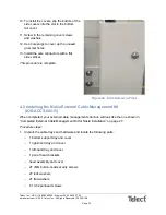
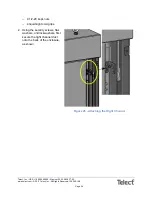
Page 29: ...procedure is complete Figure 24 Side Screws in Place 4 2 Installing the Nokia External Cable Management Kit IOE ACCS 005 G When completed your external cable management structure will look like the one shown in Completed External Cable Management Kit for Nokia Installation on page 27 Procedure steps 1 Unpack the cable trays and hardware and locate the following parts 1 bottom support tray and cove...

Page 30: ...ect com 2011 Telect Inc All Rights Reserved 139249 1 A0 4 1 2 20 keps nuts 4 liquid tight cord grips 2 Using the security screws flat washers and lockwashers first secure the right channel duct onto the back of the enclosure as shown Figure 25 Attaching the Right Channel ...

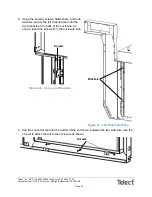
Page 31: ...k washers secure the left channel duct onto the two brackets at the back of the enclosure as shown Insert the screws from the enclosure side Figure 26 Close up of Brackets Figure 27 Left Side Installation 4 Slip the connector rail onto the bottom of the enclosure between the two side rails Use the screws to attach the rail to the enclosure as shown Brackets Screws Screws ...

Page 32: ... Bolt the brackets onto the Nokia gland plate as shown 6 Slip the gland plate assembly into the head 7 Use the 10 32 screws to secure the assembly Make sure the plate faces toward the back as shown 8 Route the cables based on your site requirements Figure 28 Brackets Figure 29 Head 10 32 screws Head 1 4 20 screws 1 4 20 screws ...

Page 33: ...nstall the covers by securing them with the M6 security screws You can installl them in any order although from the top down is ideal Your finished cable management kit should look somewhat like to the one in the following figure Figure 30 Completed External Cable Management Kit for Nokia Installation This procedure is complete ...

Page 34: ...Page 28 Telect Inc USA 1 509 926 6000 Mexico 52 33 3836 37 52 www telect com 2011 Telect Inc All Rights Reserved 139249 1 A0 This page intentionally left blank ...

Page 35: ...nd or bush ing is fitted in the hole The cables should fit snugly in the glands without gaps that may allow entry of dust and insects or other animals Insulate all neutral conductors from ground Where possible do not run AC cables parallel to other nearby DC cables Maintain adequate segregation between AC cables DC cables and low signal level alarm control wiring especially where cables enter the ...

Page 36: ...p on the rear right hand side of the enclosure 3 Thread your AC cables through a grommet and into the enclosure 4 Insert the grommet firmly into the knockout hole 5 Strip about 3 8 1 2 of jacket from the ends of the AC cables 6 Connect the incoming AC wire to the left side of the power block Line 1 top Line 2 middle Neutral bottom 7 Replace the access panel 8 Check that all of the seals are tight ...

Page 37: ...ntain or otherwise come in contact with this equipment Remove all watches and jewelry before connecting to the power supply Only use insulated tools when con necting to commercial power 6 1 Grounding the Enclosure Procedure steps 1 Make sure you have the following tools and materials Telect exterior ground lug kit part 305670 2 hole lug 1 AWG 1 2 stud 3 4 C C crimping tool for lugs digital multime...

Page 38: ...re for the location of the studs Figure 34 Grounding Points for Frame 3 Unless stated otherwise by operating company practices and guidelines connect the MGB to the site s halo ground To ground the enclosure frame follow your corporate grounding prac tices or GR 1275 The 10 position MGB holds 5 8 CC 1 4 20 studs for use with 1 2 wide lugs This procedure is complete Grounding points Front of enclos...

Page 39: ...Recycle lead acid batteries Batteries contain lead and dilute sulfuric acid Dispose of in accordance with Federal State and local regulations Do not dispose of in a landfill lake or other unauthorized location Four batteries fit into the shelf in the second compartment When you unpack the batteries inspect them for any physical damage If the batteries are damaged in any way contact the carrier Che...

Page 40: ...used Be aware that the batteries can weigh up to 150 pounds each Make sure you have precautions in place for safely lifting and moving the batteries 7 2 Battery Installation To install the batteries use the following procedure Procedure steps 1 On the battery shelf remove and temporarily set aside the battery retaining bracket and its five hex head screws optional seismic restraining equipment the...

Page 41: ...side screws first and the center screw last Figure 37 Installing the Retaining Bracket 5 Connect the battery s 48V cable to the terminal of the left most battery To connect a cable to a battery follow the manufacturer s instructions In general you can a Remove the bolt or the nut depending on the battery type from the terminal b Place the bolt or nut through the cable lug Follow manufacturer s rec...

Page 42: ...Figure 38 Connecting the Battery Cables 7 Connect the supply battery cable to the terminal of the left most battery 8 Install the battery straps provided with the batteries following the manufacturer s instructions Figure 39 48V Battery String Shown for Illustration 9 Check your wiring 10 Tighten all battery posts in accordance with the manufacturer s instructions 11 Place the temperature sensor b...

Page 43: ...LVD automatically disconnects the batteries from the load at the preset LVD disconnect voltage to prevent damage to the batteries due to excessive deep discharge The LVD reconnects the batteries automatically after the AC power is restored 7 3 Hydrogen Gas Ventilation Kit Installation Optional To prevent the build up of gas pressure install Telect s Hydrogen gas ventilation kit part 305030 Figure ...

Page 44: ... Installing the Hydrogen Gas Ventilation Kit Part 305030 Procedure steps 1 Unpack the Telect Hydrogen Gas Ventilation kit and locate the following parts one 1 4 elbow hose three 1 4 barb T hoses one 1 4 NPT male bulkhead fitting tube one 1 4 NPT brass nut 2 5 feet of polyethylene tubing one tube of silicone sealant adhesive caulk ...

Page 45: ...tery venting tubes that you are not including in the venting system Figure 41 Capping the Unused Vent Tubes 3 Cut four equal lengths of polyethylene tubing 4 Beginning with the battery farthest from the enclosure venting hole insert one of the four tubes from step 3 onto one venting tube on each battery Figure 42 Inserting the First Tubes Caps Tubes ...

Page 46: ...re venting hole 6 Insert the T shaped hos es into the other three vent tubes as shown 7 Cut three equal lengths of polyethylene tubes and connect them as shown Figure 44 Connecting the T hoses 8 Join a series of cut tubing pieces as required to reach the designated vent hole in the enclosure Figure 45 Connecting Tubes Elbow T shaped hoses Figure 43 Inserting Elbow and T shaped Hoses Tubing ...

Page 47: ...er combination Figure 46 Knockout 10 Insert the bulkhead fitting tube into the tube assembly shown in Step 8 and into the hole made in the enclosure frame in Step 9 Figure 47 Completed Hydrogen Gas Vent Kit 11 Screw the brass nut on to the bulkhead tube that is projecting from the en closure frame 12 Seal this assembly with the sealant caulk This procedure is complete Enclosure frame Tube Nut ...

Page 48: ...Page 42 Telect Inc USA 1 509 926 6000 Mexico 52 33 3836 37 52 www telect com 2011 Telect Inc All Rights Reserved 139249 1 A0 This page intentionally left blank ...

Page 49: ... cables Maintain adequate segregation between AC cables DC cables and low signal level alarm control wiring especially where cables enter the rack Cross sensitive cables e g control cables at right angles to avoid inductive coupling This includes lightning protection cables that may be on the outside of an adjacent wall Ensure your cable routing inside the rack does not interfere with access to co...

Page 50: ...lect com 2011 Telect Inc All Rights Reserved 139249 1 A0 8 2 Connecting DC Power Cables Procedure steps 1 Bring the DC load cables up through the rear left cable entry as shown in the following figure and through the grommet holes beneath it Figure 49 DC Cable Openings ...

Page 51: ...he inside of the enclosure and bring them out to the Front ac cess power termination panel through the cable entry in the front of the nrgSMART sys tem The slots in the DC load circuits correspond to the MDS module circuit breakers Figure 51 DC Power System Incoming cables Figure 50 Cables Looping Through to Front DC load circuits Common DC power return ...

Page 52: ...als terminals and conduit hardware to connect this wiring to the nrgSMART system The nrgSMART system has provisions for up to 30 digital inputs 12 digital outputs and 6 analog inputs in its basic configuration Always check your specific configuration when planning your interface and alarm connections since different configurations can have different numbers of inputs and outputs Each input and out...

Page 53: ... need to change the DO wiring on the specific I O board where that circuit originates Group 3 consists of the analog inputs at terminals 65 through 72 supporting up to 4 analog inputs The analog inputs are 0 to 10 Volts DC The remainder of the terminals are set aside for administrative and future use Use the following figures and tables as guides for configuring the 48 panel I O distribution board...

Page 54: ...edure steps 1 Bring the cables in through the top of the enclosure and through the grommet holes 2 Connect to the RJ45 female connectors Figure 54 Connecting the Wiring into the RJ45 Connectors on the I O Board 3 Connect the alarm wires to the terminal blocks depending on the configuration you want to use Figure 55 Connecting the Wiring into the Terminal Blocks This procedure is complete ...

Page 55: ...ltage is present between the ground buss in the power plant enclosure and the power plant return buss remove the rear panel on the enclosure 2 identify the return buss of the DC power plant if you cannot positively identify the return buss stop 3 Once you have identified the buss trace the power return panel cable from the return buss termination panel to the return buss 4 Remove the closest nut o...

Page 56: ...ty is correctly connected to the grounded power pin on the rear of the radio See the radio instruction manual b the grounded polarity is the positive power lead in negative 48 volt power systems so that the positive lead is connected to the radio ground indicated power plug the right side pin viewed from the rear with the ground symbol indication ...

Page 57: ...losure including the use of breakers that are UL489 listed and Square D QOB3100 or equal ALERT ALERT Do not mount any rectifiers until all cabling is completed ALERT ALERT Before you mount the rectifiers make sure the circuit breakers at the AC distribu tion panel are in the OFF position Keep each rectifier in its packaging until you are ready to mount it in the rack 9 1 Turning up the DC Power Sy...

Page 58: ...NG WARNING 3 Slide the MDS modules into the MDS slots at Layer 1 starting with the slot next to the GMT module in slot 1 The MDS modules are uniquely designed for circuit breakers and GMT circuits Installers can configure MDS modules as necessary for a given site To insert the MDS module with breaker installed per the installation instructions included with each MDS module you receive GFI Heater S...

Page 59: ...249 1 A0 a Facing the front of the enclosure position the mod ule as shown in Figure 64 You want to be sure the back end of the module matches the holes at the back of the module slot See Figures 60 and 61 Figure 59 Inserting the MDS Module Left is OFF Switch Figure 60 Inside of MDS Slot Figure 61 Rear of MDS Module ...

Page 60: ...ou should definitely feel a give when the tab is fully seated MDS documentation includes the following 10 Circuit 15A GMT Fuse Module Model MDS GMTM 10x15A Installation Guide p n 138654 Dual Circuit Breaker Module Model MDS DCBM SP100 Installation Guide p n 138646 4 Terminate the signal alarm control cables to the appropriate digital input DI digital output DO and analog input AI slots in the I O ...

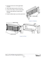
Page 61: ...Inc All Rights Reserved 139249 1 A0 the hood See I O Distribution Board on page 55 and I O Distribution Board Close up on page 55 and 8 3 Alarm and Control on page 46 Figure 63 I O Distribution Board Figure 64 I O Distribution Board Close up This procedure is complete I O distribution board ...

Page 62: ...Page 56 Telect Inc USA 1 509 926 6000 Mexico 52 33 3836 37 52 www telect com 2011 Telect Inc All Rights Reserved 139249 1 A0 This page intentionally left blank ...

Page 63: ...ed person must check the integrity of the in stalled cabling BEFORE technicians power up the DC power system ALERT ALERT DC earthing This equipment has a connection between the earthed conductor of the DC supply cir cuit and the earthing conductor Connect this equipment directly to the DC supply system earthing electrode conduc tor or to a bonding jumper from an earthing terminal bar or bus to whi...

Page 64: ...ontain hazardous energy levels Only personnel trained and experienced in DC power systems are to service this equipment Always use insulated tools Do not short circuit the live and common bus bars or cables ALERT ALERT Rectifiers To reduce the risk of electric shock and maintain optimum system cooling always cover empty rectifier slots with blanking panels To avoid electrical shock do not place ha...

Page 65: ...ls loose cables or metal objects onto intercell connections or termi nals of opposite polarity Only terminate cables and interconnecting bars after confirming that the termination will not create a short circuit Always tighten battery terminal bolts according to the battery manufacturer s specifi cation Failing to do so can cause erratic battery performance possible damage to the battery and or pe...

Page 66: ...Telecom earth cable is correctly installed DC battery and load cabling has the correct polarity A registered electrician or other suitable approved person has checked the integrity of the installed cabling All panels are in place and all empty rectifier slots are covered with blanking panels The main AC service breaker to the enclosure is properly labeled and switched OFF All AC circuit breakers f...

Page 67: ... The TE cooler fans and DAC system turn on only when the temperature is approximately 77o F or higher 6 If the Controller LED screen shows alarms ignore them at this stage 7 Check the DC output voltage and polarity of the battery string s Using a voltmeter connect the positive probe to the positive terminal and the negative probe to the negative terminal If your voltmeter is reading a POSITIVE val...

Page 68: ...ome on if the temperature is less than 50o F 21 Disable the Door Open alarm by pulling out the plunger Figures 65 68 22 Check the Controller LED screen for any alarms All alarms should be cleared after every thing is turned on If any alarms remain on see the Troubleshooting chapter in the nrg SMART 24RU Enclosure IOE 24S XXXX User Manual Telect part number 138655 23 Push the Door Open alarm plunge...

Page 69: ...C load cables must also comply with the following general specifications Conductor Copper stranded single core Temperature rating 194 F 90 C minimum NOTE Part numbers are for FCI BURNDY products In the US or Canada use these parts or equivalent UL listed crimp lugs Table 2 Cable Sizes Circuit breaker rating Cable size Metric cable size equivalent minimum Crimp lug Crimping Tool Crimp tool die 2A 1...

Page 70: ...Page 64 Telect Inc USA 1 509 926 6000 Mexico 52 33 3836 37 52 www telect com 2011 Telect Inc All Rights Reserved 139249 1 A0 This page intentionally left blank ...

Page 71: ...n or fan controller Check power distribution panel output to both fan and fan controller for 27V and ground Faulty fan s Seized bearings or no tachometer output to fan controller Replace fan s Faulty fan controller Replace fan controller board Reduced air flow into enclosure Dirty filter Replace or clean air filter Noisy fan Fan not properly aligned Loosen mounting screws and adjust alignment Faul...

Page 72: ... rectifier position Check AC connections If the second recti fier operates normally the first rectifier is faulty and must be returned for service All rectifier LEDs flash The rectifier Identify function Normal operation Rectifier yellow LED flashes The system controller is start ing Wait for system controller to complete start up Rectifier has not registered with the system controller Remove then...

Page 73: ...ter AC supply failure Check that the battery has recharged within the expected time High system output voltage Equalize Fast Charge and or Temperature Compensation is active Disable active function s in system controller if not required Incorrect float voltage setting at system controller Correct the float voltage setting of the system controller Record new setting Faulty rectifier Locate the rect...

Page 74: ...Check that the I O board is connected Power LED is on Check that the LVD control and power cables are connected See Connections on page 4 Check the connections from the battery bus to the LVD Table 6 Troubleshooting issues and actions I O board Problem Possible cause Required action I O board Power Comms OK LED is off I O board is not powered or faulty Check connection to YH3 on I O board Replace ...

Page 75: ...the wrong state SC200 internal state does not match signal from contactor auxiliary switch Check the electrical and mechanical operation of the contactor and auxiliary switch Check all wiring and connectors LVD contactor s is not operating LVD settings are incorrect Check that the LVD is enabled and set to correct values Check that the LVD manual control is set to AUTO Check that the contactor is ...

Page 76: ...Manager II See 4 1 3 Grounding in the St Louis Market Area on page 75 Unable to change settings from SC200 keypad A previous setting change is still being updated Wait a short time then try again Keypad access is set to Protected or PIN Protected To temporarily enable keypad access when access is set to Protected Press Up and Down keys together for approxi mately 10 seconds NOTE Keypad access is n...

Page 77: ... normal operation SC200 or DCTools Web displays or N A Failed disconnected or unconfigured sensor Replace connect or configure sensor Faulty or disconnected voltage feed module Replace or connect voltage feed module Incorrect I O board mapping Check I O board mapping To re map I O boards 1 In DCTools Web go to I O Board I O Board to Serial Number Mapping 2 Copy the I O board serial number s from t...

Page 78: ...ad from www powerware com downloads Password required to change settings To set a Write Access Password 1 Connect to the SC200 with DCTools Web 2 Go to Configuration Communications 3 Type a password into the Write Access Pass word field NOTE Passwords are case sensitive maximum 32 characters 4 Click Apply Changes To clear or change a Write Access Password 1 Connect to the SC200 with DCTools Web 2 ...

Page 79: ...s assigned by the network administrator 3 If required set HTTP Access to Enabled for web browser access or set HTTPS Access to Enabled for secure web access To configure an SC200 for Ethernet communica tions using DCTools 1 Connect using a USB 2 In DCTools go to Configuration Communica tions 3 Under Ethernet enter the IP Address Subnet Mask and Gateway Address assigned by the net work administrato...

Page 80: ... cannot change settings Backup or Restore Execute Com mands Upgrade Firm ware or Edit User List Check the user s access levels SC200 time date in DCTools Web is incorrect Time needs to be set To set the clock 1 Connect to the SC200 via a web browser 2 Go to Configuration Time 3 Click on the time date field to select the text 4 Select the time or date text to be changed and type the correct time da...

Page 81: ...the two nuts currently holding the return cable to the bus to be removed without loosening the return connection Remove this nut 4 Land the grounding cable 5 Reinstall and torque the nut 6 Land the two hole end of the grounding cable on the most convenient position on the cabinet buss bar at the rear left behind the power plant and torque the nuts 7 Reinstall the rear cabinet panel 4 1 4 Microwave...

Page 82: ...MT return terminal and the right side noted by the ground symbol of the radio power input 4 Verify that the supply side power supply hot is on the GMT supply terminal and the left side of the radio power input 5 Install a 6 ground wire green with yellow strip from the ground terminal on the radio rear to the cabinet s ground buss or frame Painted contact areas must be sanded to remove the paint wh...

Reviews: