18
Teledyne API Model 465H O
3
Monitor User Manual
06161H DCN7969
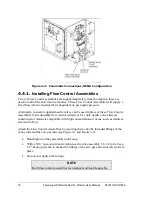
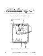
Figure 4-4: Pneumatic Connections, NEMA Configuration
4.4.1.
Installing Flow Control Assemblies
Two (2) Flow Control assemblies are supplied separately from the monitor, these are
used to control the flow into the monitor. These Flow Control Assemblies will supply a
fixed flow into the monitor that is dependent on gas supply pressure.
Alternately, customer supplied needle valves can be used in place of these Flow Control
Assemblies if an adjustable flow control is desired. Use only needle valves that are
constructed of materials compatible with high concentrations of ozone, such as stainless
steel and Teflon.
Attach the Flow Control Assemblies by screwing them onto the threaded fittings of the
ozone inlet and the zero gas inlet (see Figure 9-1 and Figure 9-2).
Hand-tighten orifice assemblies until snug.
With a 9/16” open-end wrench, tighten each orifice assembly 1/8–1/4 turn. Use a
1/2” back-up wrench to anchor the fittings of the zero gas and ozone inlet ports in
place.
Do not over tighten the fittings.
NOTE
Both flow control assemblies are identical and interchangeable.
Summary of Contents for 465H
Page 2: ......


