09419A DCN8342
Teledyne API Model 480L O
3
Monitor User Manual
53
7.9 DISPLAY ASSEMBLY REPLACEMENT
In the event that the front panel display assembly requires replacement due to
damage caused by wear and tear or aging, these procedures provide instructions for
its careful removal and replacement. This is especially important if there is any
damage to the mask, compromising the seal and allowing moisture or other matter
to infiltrate the enclosure.
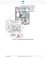
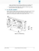
Refer to Figure 7-6 for for the following procedures:
1.
Disconnect power from the instrument using proper lockout/tagout procedures
per site requirements, and carefully open enclosure panel per cautionary
message at start of this Maintenance and Adjustments section.
2.
Detach the display cable from the mainboard (pinouts for all four connectors are
the same, so placement doesn’t matter).
3.
Free the display cable from the securing clips.
4.
Carefully remove the EMI core from the enclosure and remove any remaining
adhesive from the door.
5.
Using a Star T10 screwdriver, remove the screws securing the display bezel to
the door.
6.
Discard the old display bezel with cable per local regulations for electronic
waste.
7.
Ensure gasket is located in the outer groove of the replacement bezel.
8.
String the replacement bezel’s display cable through the open window while
aligning the bezel with the screw holes on the enclosure door, and start each
screw by a few turns.
9.
Once all the screws are started, apply a sequence-based tightening pattern to
ensure even preload distribution so that the gasket gets equal compression on all
sides, until the bezel is completely flush to the door.
10.
Route the display cable through the plastic retainers, locating the ferrite core in
the center of the display.
11.
Remove the tape backing from the ferrite core and press the ferrite core onto the
door until well bonded.
12.
Plug the display cable into the mainboard.
Summary of Contents for 480L
Page 2: ......

