54
Teledyne API Model 480L O
3
Monitor User Manual
09419A DCN8342
13.
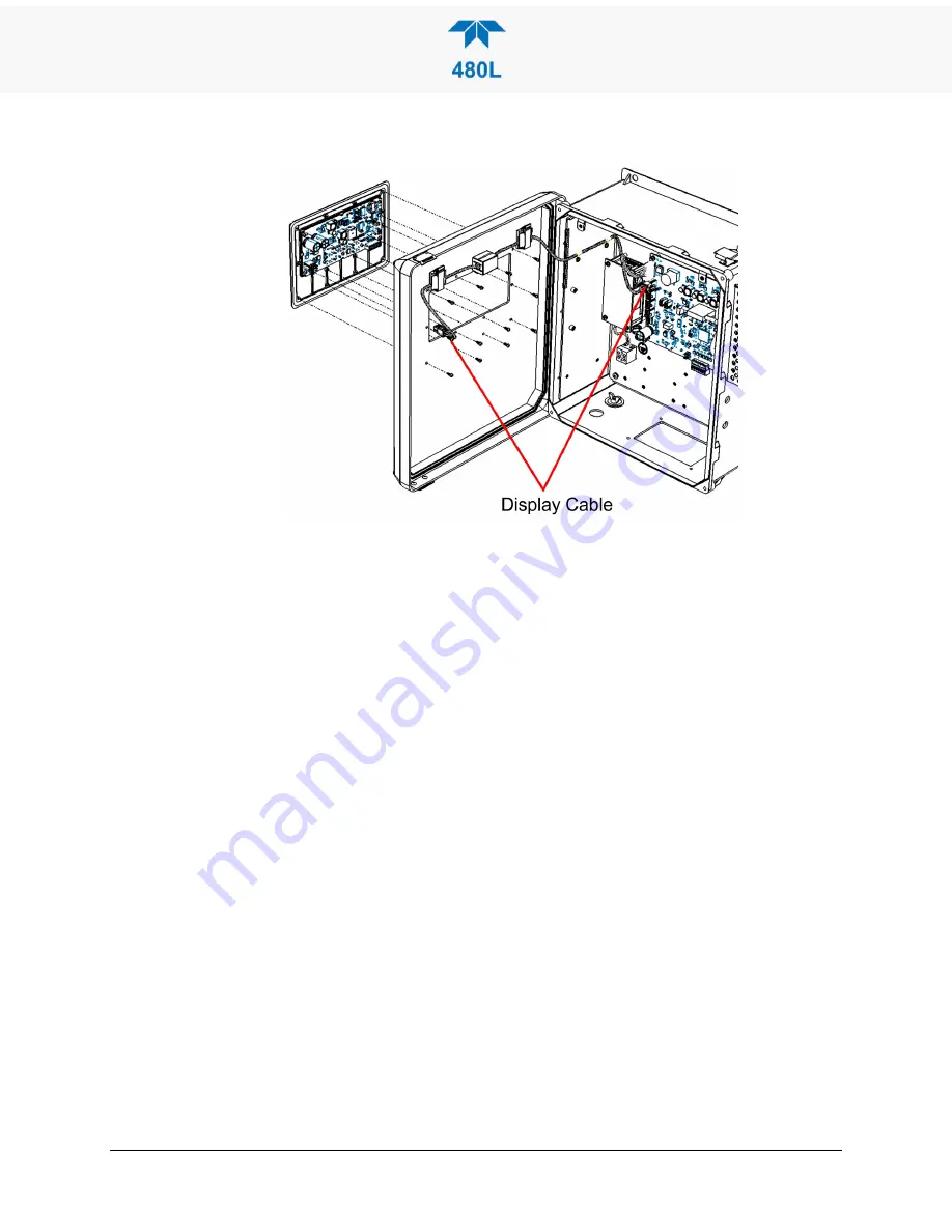
Power up the instrument and confirm that the display and control keys are
functioning properly.
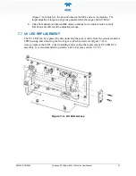
Figure 7-6. Display Assembly Removal
7.10 CLEANING EXTERIOR SURFACES
If necessary, the front panel mask and keyboard can be cleaned with a damp cloth.
Do not attempt to clean any of the other surfaces of the instrument. Do not
submerge any part of the instrument in water or cleaning solution.
7.11 REMOVING/INSTALLING RELAY EXPANSION BOARD
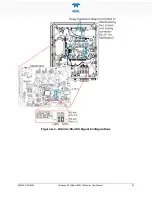
If the Relay Expansion Board option is installed, it must be removed in order to
access the configuration pins for configuring either Analog output (Figure 3-5) or
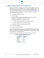
Serial communications (Figure 6-1).
1.
Power off the instrument.
2.
Locate the relay expansion board (Figure 3-5 or Figure 6-1), and remove the
four screws.
3.
Disconnect the relay expansion board pins from the Mainboard J11 connector
(keyed for correct board alignment).
4.
Lift the relay expansion board from the expansion posts to make adequate
room to access the shunt selection for both the Analog (J15-J17) and the Serial
Communication (J20, J23) jumper pins.
5.
Replace the expansion board by aligning the pins to the J11 connector. The
connector is keyed to help with correctly lining up the pins, carefully engage
the pins and press down the relay board.
6.
Secure the board in place by re-installing the same four (#6-32x3/8”) screws
into the expansion posts.
Summary of Contents for 480L
Page 2: ......

