Teledyne API M751H High Performance Zero Air Generator
Getting Started
07773B DCN6940
15
3.4 Electrical and Pneumatic Connections
3.4.1 ELECTRICAL
NOTE
To maintain compliance with EMC standards, it is required that the power cord
length be no greater than 3 meters.
With the power switch in the “OFF” position, connect the power cord from the AC
input connection to the proper power source.
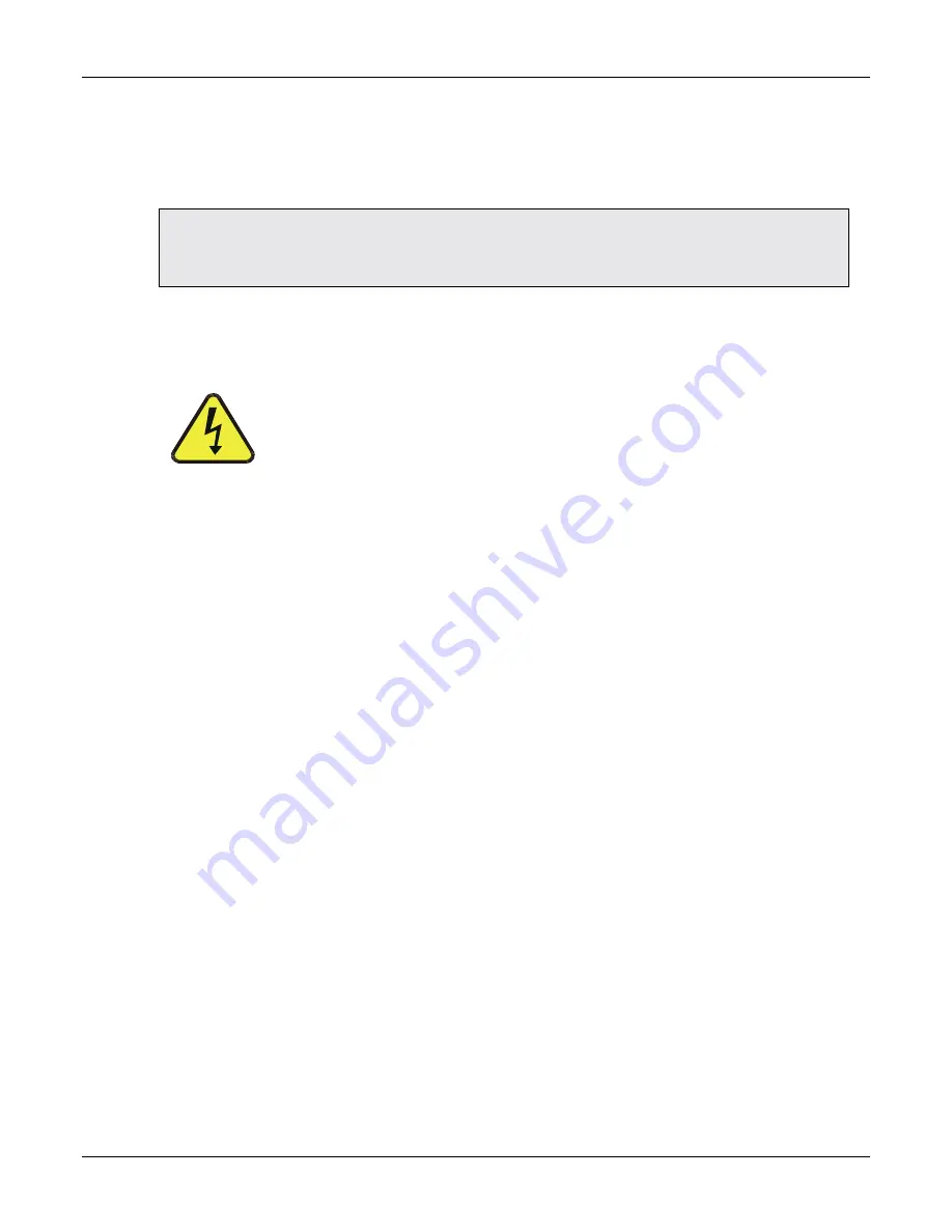
CAUTION
ENSURE THAT THE POWER CORD IS PROPERLY GROUNDED
AND ADEQUATELY RATED FOR THE SPECIFIED POWER
RATING OF THIS INSTRUMENT (SEE SPECIFICATIONS TABLE)
.
3.4.2 PNEUMATICS
Make the following pneumatic connections:
DRAIN
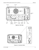
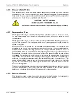
(1/4” swage-type bulkhead union) - Connect 1/4” diameter tubing to the water-
out fitting (refer to Figure 4-2) to avoid the occasional spurts of water ejecting from
the fitting. Ensure the tubing is long enough that the water ejects outside the
instrument.
ZERO AIR OUT
(1/4” swage-type bulkhead union) - Connect the AIR OUT port of the
751H to the INLET fitting of the Model 700 Calibrator with
clean
1/4” TFE tubing.
Keep this line as short as possible to minimize pressure drops. . The pressure in this
line is adjustable, but should normally be 30 ± 5 psig.
Summary of Contents for 751H
Page 2: ......
Page 4: ...ii 07773B DCN6940 This page intentionally left blank...
Page 44: ...A 2 07773B DCN6940 This page intentionally left blank...
Page 46: ...This page intentionally left blank A 4 07773B DCN6940...
Page 47: ...07773B DCN6940 B 1 APPENDIX B SCHEMATICS...
Page 48: ...B 2 07773B DCN6940 This page intentionally left blank...

