background image

Teledyne API M751H High Performance Zero Air Generator  

MAINTENANCE


07773B DCN6940  


31 


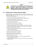
WARNING 

EVEN THOUGH THE INSTRUMENT PANEL  POWER SWITCH IS 
OFF, THERE IS LINE VOLTAGE PRESENT AT THE POWER ENTRY 
TERMINALS, POWER SWITCH TERMINALS AND ON  THE 
CONTROL BOARD. FOR ADDED SAFETY, REMOVE THE POWER 
CORD FROM THE INSTRUMENT PANEL RECEPTACLE.


5.5   Replacing the Charcoal Scrubber Media 

Before emptying the used charcoal, wearing a dust mask is recommended  as a 
preventive measure since it is possible that some charcoal dust  may rise when 
emptying and refilling the canister. 

1.  Turn off the 751H and wait for the pressure to go to zero. 

2.  Remove the 1/4” tubing connected to the top of the scrubber canister. 

3.  Release the fastening strap to free the canister. 

4.  Remove the 1/4” tubing connected to the bottom of the canister. 

5.  Unscrew the cap of the canister. 

6.  Remove the pad from the top of the canister. 

7.  Pour out the charcoal and dispose of it properly. 

8.  Refill the canister with fresh charcoal, up to 3/8” to 1/4” from the top. Rap the 

sides of the canister gently to settle the charcoal and add more as necessary. 

9.  Replace the pad on top of the charcoal. 

10. Wipe any charcoal dust from the top edge of the canister. This is the surface 

which seals against the gasket. 

11. Check that the gasket is in place in the cap. 

12. Replace the cap and tighten it “hand-tight”. 

13. Reconnect the lower 1/4” tube connection. 

14. Reattach the canister with the fastening strap. 

15. Reconnect the upper 1/4” tube. 

16. Enable “maintenance mode” (Section 5.2) which will bypass the dewpoint 

warnings during scrubber drying. 

17. After the compressor is turned on, it may be wise to check the scrubber for leaks 

(see Section 5.11)

Summary of Contents for 751H

Page 1: ...ATOR TELEDYNE API 9970 CARROLL CANYON ROAD SAN DIEGO CA 92131 1106 USA Toll free Phone 800 324 5190 Phone 1 858 657 9800 Fax 1 858 657 9816 Email api sales teledyne com Website http www teledyne api c...

Page 2: ......

Page 3: ...are Parts List Appendix A of this manual 078370100 A Model 751H Interconnect List Appendix B of this manual 07837 A Model 751H Interconnect Diagram Appendix B of this manual NOTE Please read this manu...

Page 4: ...ii 07773B DCN6940 This page intentionally left blank...

Page 5: ...e combustible gas es Note For Technical Assistance regarding the use and maintenance of this instrument or any other Teledyne API product contact Teledyne API s Technical Support Department Telephone...

Page 6: ...EN GARDE Surface chaude Ne pas toucher Toucher certaines parties de l instrument sans protection ou sans les outils appropri s pourrait entra ner des dommages aux pi ces ou l instrument Pictogramme t...

Page 7: ...manufacturer s warranty Product Return All units or components returned to Teledyne API should be properly packed for handling and returned freight prepaid to the nearest designated Service Center Aft...

Page 8: ...G 13 3 2 INSTALLATION 13 3 3 INSTRUMENT PANEL 14 3 4 ELECTRICAL AND PNEUMATIC CONNECTIONS 15 3 4 1 ELECTRICAL 15 3 4 2 PNEUMATICS 15 3 5 POWER UP 16 3 6 STORAGE AND TRANSPORTATION 16 3 7 EXPENDABLE KI...

Page 9: ...UBBER MEDIA 31 5 6 REPLACING THE NO NO2 SCRUBBER MEDIA 32 5 7 REPLACING THE CO SCRUBBER 32 5 8 REPLACING THE HYDROCARBON HC SCRUBBER 33 5 9 SERVICING THE REGENERATIVE DRYER 34 5 10 CHANGING THE REGENE...

Page 10: ...viii 07773B DCN6940 LIST OF TABLES TABLE 2 1 SPECIFICATIONS 11 TABLE 4 1 POWER AND DEWPOINT CONDITION INDICATORS 27 TABLE 5 1 MAINTENANCE SCHEDULE 29 TABLE 6 1 TROUBLESHOOTING 39...

Page 11: ...through a final filter to assure a clean dry analytical zero air supply The regenerative dryer removes water and produces gas with a dewpoint of less than 20 C up to 10 SLPM flow rate independent of...

Page 12: ...Introduction Teledyne API M751H High Performance Zero Air Generator 10 07773B DCN6940 This page intentionally left blank...

Page 13: ...x 351 mm Weight 47 lbs 21 3 kg Operating Temp 5 40 C Power Typical Power Consumption 110 120 V 60 Hz 4 0 A 220 240 V 50 Hz 3 0 A 320 W 425 W Environmental Conditions Installation Category Over Voltage...

Page 14: ...those requirements and directives For additional certifications please contract Technical Support at 1 800 324 5190 or sda_techsupport teledyne com 2 2 1 Safety IEC EN 61010 1 2010 3rd Edition Safety...

Page 15: ...shipping damage If there are signs of damage immediately advise the shipper then Teledyne API 3 Open the lid and check for damage inside 4 Check the line voltage and frequency label on the instrument...

Page 16: ...51H High Performance Zero Air Generator 14 07773B DCN6940 3 3 Instrument Panel Figure 3 1 shows the components in the Model 751H instrument layout that are pertinent to starting up the instrument Figu...

Page 17: ...SPECIFIED POWER RATING OF THIS INSTRUMENT SEE SPECIFICATIONS TABLE 3 4 2 PNEUMATICS Make the following pneumatic connections DRAIN 1 4 swage type bulkhead union Connect 1 4 diameter tubing to the wat...

Page 18: ...ument panel pressure gauge should read 30 psig 6 When the DEWPOINT LED is lit green it indicates that the 751H is producing clean dry air see Specifications footnote Table 2 1 NOTE If the 751H has bee...

Page 19: ...r shipment 3 7 Expendable Kits OPT 42A A one year supply of replacement particulate filters and consumable scrubber media is available from Teledyne API as Option 42A Refer to Appendix B for a list of...

Page 20: ...Getting Started Teledyne API M751H High Performance Zero Air Generator 18 07773B DCN6940 This page intentionally left blank...

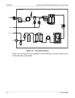
Page 21: ...e water to be expelled through a drain fitting The partially dried air enters the Regenerative Dryer which removes essentially all the remaining water and a portion of the other contaminants The press...

Page 22: ...Regen Dryer Inlet Filter B A Pressure Gauge 0 60 30 HC Scrubber Purafil Scrubber Charcoal Scrubber CO Scrubber DFU Filter ZERO AIR OUT Cooling Coil Dewpoint Sensor DRAIN OUT Relief Valve Coalescer Pr...

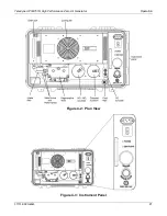
Page 23: ...Teledyne API M751H High Performance Zero Air Generator Operation 07773B DCN6940 21 Figure 4 2 Plan View Figure 4 3 Instrument Panel...

Page 24: ...ressor is mounted on a sub plate which is supported on four tuned vibration isolators 4 2 3 Cooling Coil The cooling coil consists of several turns of copper tubing coiled through which the cooling fa...

Page 25: ...cts high pressure air to one of the two columns and vents the other column to atmosphere Virtually all the water in the high pressure air is trapped by the molecular sieve A portion of the dried air i...

Page 26: ...ber and the pelletized precious metal catalyst The cartridge is heated by a band heater with an integral type K thermocouple and is housed in a stainless steel casing with appropriate thermal insulati...

Page 27: ...final filter located adjacent to the instrument panel retains any particulates released by the 751H The filter rating is 99 99 removal of 0 1 micron particles If the filter becomes restricted it shoul...

Page 28: ...wing functions Cycles the four way valve of the Regenerative Dryer Cycles the water drain solenoid valve Cycles the relief valve in response to the pressure sensor Cycles the Regenerative Dryer four w...

Page 29: ...point indicator on the instrument panel will light green indicating that the air is dry 4 2 18 Instrument Panel Indicator Lights Multicolor indicator lights for both the power state and dewpoint state...

Page 30: ...Operation Teledyne API M751H High Performance Zero Air Generator 28 07773B DCN6940 This page intentionally left blank...

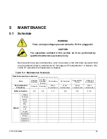
Page 31: ...ons for Storage and Transportation in Section 3 6 Table 5 1 presents the maintenance schedule Table 5 1 Maintenance Schedule Date Instrument was received _____________________ Item Charcoal Scrubber N...

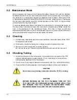
Page 32: ...t instrument with a small diameter through the hole and press the button 5 3 Cleaning 1 Occasionally depending upon the local conditions check the inside of the 751H for excessive dirt or dust 2 Parti...

Page 33: ...nister 4 Remove the 1 4 tubing connected to the bottom of the canister 5 Unscrew the cap of the canister 6 Remove the pad from the top of the canister 7 Pour out the charcoal and dispose of it properl...

Page 34: ...the panel 1 Turn off power and unplug the 751H 2 Remove the Charcoal and NO NO2 scrubbers to gain access to the hardware 3 Disconnect the tubing and remove the four screws to remove the scrubber CAUT...

Page 35: ...e chassis 6 Lift out the scrubber 7 Install a new Teledyne API supplied scrubber these are purged at the factory and tighten the four captive screws 8 Attach and tighten the pneumatic connections CAUT...

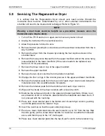
Page 36: ...10 for procedures 7 Remove the three nuts on top of the upper manifold 8 Remove the upper manifold 9 Remove the two dryer columns from the bottom manifold 10 Change the four o rings in the circular gr...

Page 37: ...THEM 23 Push down hard in the center of the upper manifold with one hand and finger tighten the nuts until you feel a soft resistance 24 With a wrench tighten each nut in turn 1 2 turn at a time This...

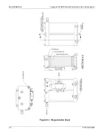
Page 38: ...MAINTENANCE Teledyne API M751H High Performance Zero Air Generator 36 07773B DCN6940 Figure 5 1 Regenerative Dryer...

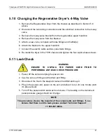
Page 39: ...d two pneumatic fittings 8 Re install the dryer in the 751H chassis and tighten the four captive base screws 5 11 Leak Check WARNING ENSURE TO UNPLUG THE POWER CORD PRIOR TO PERFORMING ANY LEAK CHECK...

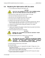
Page 40: ...p to the filter housing and secure in place with a clockwise turn If the screen is damaged then replace the intake filter assembly TAPI P N FL51 5 12 2 Final Filter To replace the disposable Final fil...

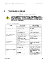
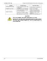
Page 41: ...aker Reset power switch circuit breaker Compressor does not start after 10 seconds AIR IN filter is plugged Clean or replace the filter Compressor fan is jammed Check for any mechanical obstruction Pu...

Page 42: ...contaminated Replace the scrubbers Output air is not dry 4 way valve is jammed only one column is being used Check to ensure the valve is plugged in replace the valve Reflux flow controller is plugge...

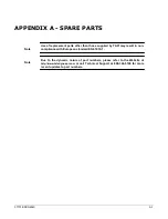
Page 43: ...than those supplied by TAPI may result in non compliance with European standard EN 61010 1 Note Due to the dynamic nature of part numbers please refer to the Website at http www teledyne api com or c...

Page 44: ...A 2 07773B DCN6940 This page intentionally left blank...

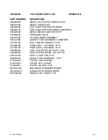
Page 45: ...ASSEMBLY 057270000 GASKET FOR SCRUBBER CANISTERS 077830100 PCA CONTROL BOARD 751H 077990000 PUMP ASSY 115V 60HZ 751H 077990100 PUMP ASSY 230V 50HZ 751H 078580000 ASSY WATER DROP VALVE 751H 078600000 A...

Page 46: ...This page intentionally left blank A 4 07773B DCN6940...

Page 47: ...07773B DCN6940 B 1 APPENDIX B SCHEMATICS...

Page 48: ...B 2 07773B DCN6940 This page intentionally left blank...

Page 49: ...ted without proper authorization Printed Documents are Uncontrolled Everywhere look ADVANCED POLLUTION INSTRUMENTATION J1 DC AC J7 FAN FA10 J11 J17 J3 HEATER SCRUBBER PUMP J1 J8 J2 J2 J1 J15 J19 07783...

Reviews: