MAINTENANCE
Teledyne API M751H High Performance Zero Air Generator
34
07773B DCN6940
5.9 Servicing The Regenerative Dryer
It is unlikely that the Regenerative Dryer should ever need service. Should the
molecular sieve become contaminated by oil or other external contaminants, the
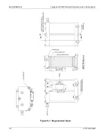
scrubber will need to be cleaned and recharged. Refer to Figure 5-1.
NOTE
Wearing a dust mask could be helpful as a preventive measure since the
molecular sieve may be dusty.
1. Turn off the 751H and turn on again and remove any water in bowl.
2. Unplug the instrument from electrical service.
3. Allow the pressure to bleed to zero.
4. Remove the two pneumatic connections and the electrical connection from the 4-
way manifold.
5. Remove the dryer from the chassis by undoing the four captive screws in the
scrubber base.
6. Remove the 4-way valve bracket from the upper manifold and let the valve hang
loose attached to the lower manifold. (If the valve needs to be replaced, see
Section 5.10 for procedures).
7. Remove the three nuts on top of the upper manifold.
8. Remove the upper manifold.
9. Remove the two dryer columns from the bottom manifold.
10. Change the four o-rings in the circular grooves in the upper and lower manifolds.
11. Remove the retainer pads from the top end of each dryer column and dump the
molecular sieve into a suitable waste receptacle.
12. Remove the retainer pads from the bottom end of each dryer column.
13. Wipe out the inside of the dryer columns with a clean dry cloth.
14. Examine the surface and ports in the upper and lower manifolds. If there is an
accumulation of dirt or corrosion, disassemble the manifolds and clean them. If
not, proceed with the next step.
15. Place new, clean retainer pad in the bottom end of each dryer column, pushing
in until the pads are at the retainer rings.
16. Invert the columns so that the open ends (top) are up.
17. Pour new, clean molecular sieve into each column, up to 1/4” from the top. Rap
the side gently, (with a screw-driver handle, for instance) to settle the molecular
sieve, and then top up to the 1/4” mark again.
18. Place new, clean retainer pads into the top of each column to the retainer ring.
Summary of Contents for 751H
Page 2: ......
Page 4: ...ii 07773B DCN6940 This page intentionally left blank...
Page 44: ...A 2 07773B DCN6940 This page intentionally left blank...
Page 46: ...This page intentionally left blank A 4 07773B DCN6940...
Page 47: ...07773B DCN6940 B 1 APPENDIX B SCHEMATICS...
Page 48: ...B 2 07773B DCN6940 This page intentionally left blank...

