Introduction
Teledyne API – Model T108 Addendum to T100 Manual
12
07268C DCN8258
1.5. INSTALLATION
The T108 consists of two chassis: the analyzer and the converter. There is a power cord for each that
should be plugged into the correct AC mains receptacle. See the model label on the rear panel of each
chassis for the voltage and frequency configuration. The power connection must be made with an
approved three-wire-grounded power cord.
The pneumatic connections are shown in Figure 1-5 .
•
Connection to the TS analyzer must be made with Teflon tubing.
•
Connect the sample inlet to the labeled fitting.
•
The sample exhaust must be routed to a well-ventilated area away from the air inlet for the zero air
scrubber on the rear panel.
CAUTION! Ensure proper ventilation to the converter!
Do not block the side or the back of the Model 501 TS Converter!
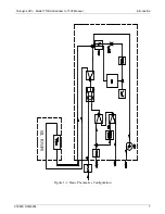
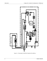
The overall pneumatic diagrams of the Model T108 are shown in Figure 1-1, Figure 1-2 , and Figure 1-3.
CAUTION!
Do not operate without the 501TS converter’s cover in place! Oven
temperature will not regulate properly without cover properly installed.
Summary of Contents for T108 Series
Page 2: ......
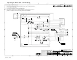
Page 26: ...Appendix A Model 501 Interconnects 07268C DCN8258...

