Teledyne API – Model T300/T300M CO Analyzer
Getting Started
71
1
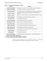
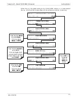
This will match the currently selected units of measure for
the range being displayed.
2
Only appears if CO
2
sensor option is installed.
3
Only appears if O
2
sensor option is installed.
4
The
STABILE
function can be set to display data related
to any of the gasses the analyzer measures, e.g. (if either
the CO
2
or the O
2
sensor options are installed).
5
Only appears if analog output
A4
is actively reporting a
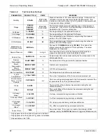
TEST FUNCTION
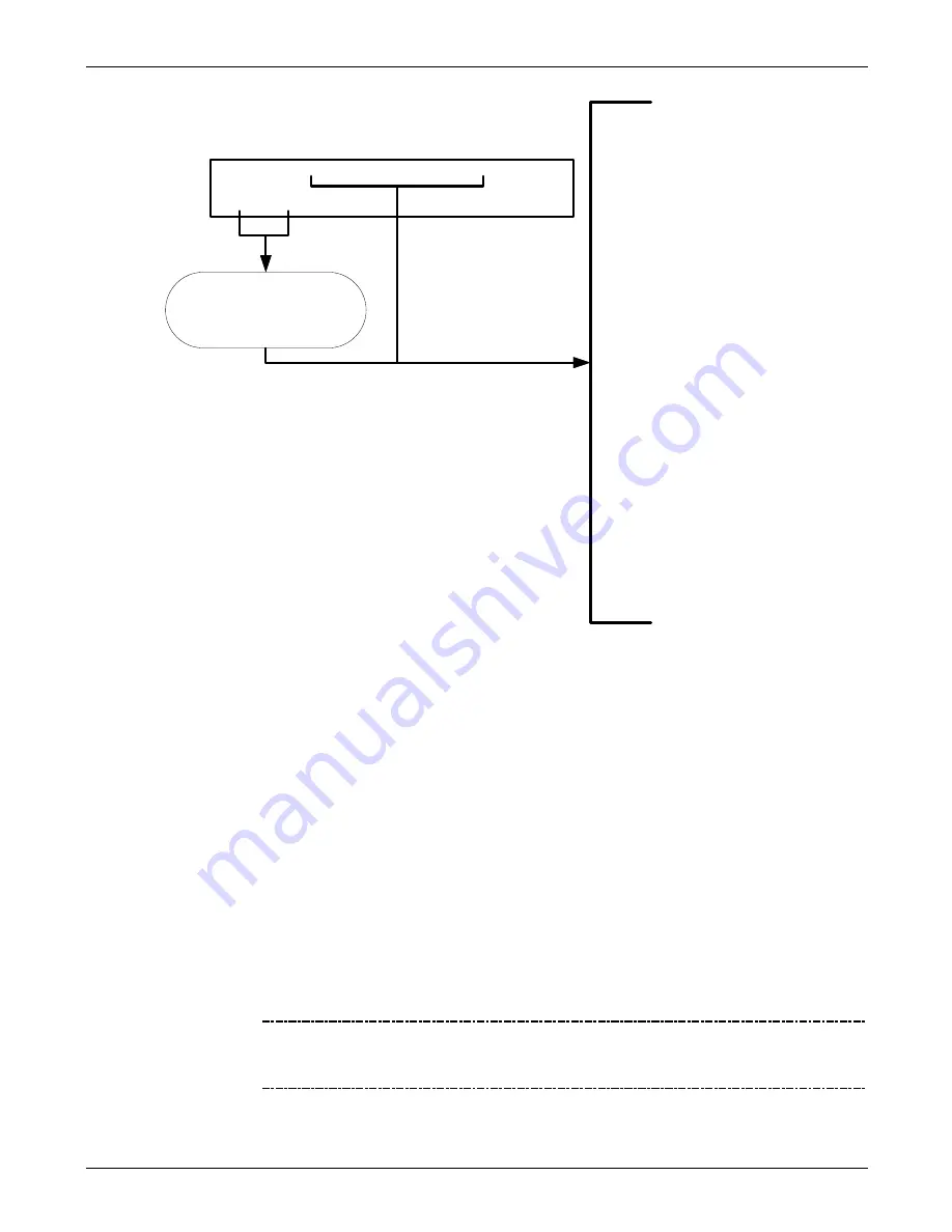
SAMPLE
RANGE=50.0 PPM CO= XX.XX
<TST
TST> CAL
SETUP
Toggle
<TST TST>
to scroll through list of
functions.
•
RANGE=[Value]PPB
1
•
RANGE1=[Value]PPB
1
•
RANGE2=[Value]PPB
1
•
CO2 RANGE=[Value]%
2
•
O2 RANGE=[Value]%
3
•
STABIL=[Value]PPM
4
•
COMEAS =[Value]MV
•
COREF =[Value]MV
•
MR RATIO =[Value]
•
PRESS =[Value]IN-HG-A
•
SAMP FL=[Value]CC/M
•
SAMPLE TEMP=[Value]ºC
•
BENCH TEMP=[Value]ºC
•
WHEEL TEMP=[Value]ºC
•
O2 CELL TEMP=[Value]ºC
3
•
BOX TEMP=[Value]ºC
•
PHT DRIVE =[Value]MV
•
SLOPE=[Value]
•
OFFSET=[Value]MV
•
CO2 SLOPE=[Value]
2
•
CO2 OFFSET=[Value]MV
2
•
O2 SLOPE=[Value]
3
•
O2 OFFSET=[Value]MV
3
•
TEST=[Value]MV
5
•
TIME=[HH:MM:SS]
3.4.4.
INITIAL CALIBRATION
To perform the following calibration you must have sources for zero air and span gas
available for input into the sample port on the back of the analyzer. See Section 3.3.2
for instructions for connecting these gas sources.
The initial calibration should be carried out using the same reporting range set up as
used during the analyzer’s factory calibration. This will allow you to compare your
calibration results to the factory calibration as listed on the
Final Test and Validation
Data Sheet
.
If both available DAS parameters for a specific gas type are being reported via the
instruments analog outputs e.g.
CONC1
and
CONC2
when the
DUAL
range mode is
activated, separate calibrations should be carried out for each parameter.
•
Use the
LOW
button when calibrating for
CONC1
(equivalent to
RANGE1
).
•
Use the
HIGH
button when calibrating for
CONC2
(equivalent to
RANGE2
).
NOTE
The following procedure assumes that the instrument does not have any
of the available Valve Options installed. See Section 9.3 for instructions
for calibrating instruments that have valve options.
06864D DCN7562
Summary of Contents for T300
Page 2: ......
Page 182: ...06864D DCN7562 ...
Page 227: ...225 This page intentionally left blank 06864D DCN7562 ...
Page 228: ...06864D DCN7562 ...


