60
Teledyne API T500U CAPS NO
2
Analyzer with NumaView™ Software
083730510A DCN8172
MANUAL ADJUSTMENT OF CURRENT RANGE ANALOG OUTPUTS
These instructions assume that the Current Loop Option is installed (Section 2.3.1.3).
This
option places circuitry in series with the output of the D-to-A converter on the
motherboard that changes the normal DC voltage output to a 0-20 milliamp signal.
Adjusting the signal zero and span levels of the current loop output is done by raising or
lowering the voltage output of the D-to-A converter circuitry on the analyzer’s
motherboard. This raises or lowers the signal level produced by the current loop option
circuitry.
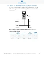
The software allows this adjustment to be made in 100, 10 or 1 count increments. Since
the exact amount by which the current signal is changed per D-to-A count varies from
output-to-output and instrument–to–instrument, you will need to measure the change in the
signal levels with a separate, current meter placed in series with the output circuit. See
Figure 2-4 for pin assignments and diagram of the analog output connector.
mADC
IN OUT
Recording
Device
I IN +
I
IN -
ANALYZER
I OUT +
I
OUT -
Current
Meter
Figure 2-43. Setup for Checking / Calibration Current Output Signal Levels
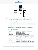
An alternate method for measuring the output of the Current Loop converter is to connect
a 250 ohm
±
1% resistor across the current loop output in lieu of the current meter (see
Figure 2-4 for pin assignments and diagram of the analog output connector). This allows
the use of a voltmeter connected across the resistor to measure converter output as VDC or
mVDC.
CAUTION!
Do not exceed 60 V peak voltage between current loop
outputs and instrument ground.
Summary of Contents for T500U
Page 2: ......

