96
Teledyne API T500U CAPS NO
2
Analyzer with NumaView™ Software
083730510A DCN8172
F
AULT
D
IAGNOSIS
W
ITH
D
ASHBOARD
F
UNCTIONS
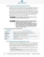
In addition to being useful as predictive diagnostic tools, the functions viewable in the
Dashboard can be used to isolate and identify many operational problems when combined
with a thorough understanding of the analyzer’s principles of operation (see Section 6).
The acceptable ranges for these functions are listed in the “Nominal Range” column of the
analyzer
Final Test and Validation Data Sheet
shipped with the instrument. Values outside
these acceptable ranges indicate a failure of one or more of the analyzer’s subsystems.
Functions whose values are still within acceptable ranges but have significantly changed
from the measurement recorded on the factory data sheet may also indicate a failure.
Make note of these values for reference in troubleshooting.
Note
If no value displays for any of these Dashboard functions, it
indicates an OUT OF RANGE reading.
Note
Sample Pressure measurements are represented in terms of
“Absolute Atmospheric Pressure” because this is the least
ambiguous method for reporting gas pressure.
Absolute atmospheric pressure is about 29.92 in-Hg-A at sea
level. It decreases about 1 in-Hg per 1000 ft gain in altitude. A
variety of factors such as air conditioning systems, passing
storms, and air temperature, can also cause changes in the
absolute atmospheric pressure.
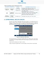
Table 5-4. Dashboard Functions - Indicated Failures
DASHBOARD
FUNCTION
INDICATED FAILURE(S)
Box Temp
Environment out of temperature operating range; broken thermistor
IZS Temp (option)
Malfunctioning heater; relay board communication (I
2
C bus); relay burnt out
Manifold Temp
Manifold temperature out of range; broken thermistor.
Oven Temp
Oven temperature out of range; broken thermistor.
Sample Pressure
Leak; malfunctioning valve; malfunctioning pump; clogged flow orifices; sample inlet
overpressure
Sample Temp
Sample temperature out of range; broken thermistor.
Stability
Unstable concentrations; leaks
U
SING THE
D
IAGNOSTIC
S
IGNAL
I/O
F
UNCTIONS
The signal I/O functions in the Utilities>Diagnostics menu allows access to the digital and
analog I/O in the analyzer. Some of the digital signals can be controlled through the Setup
menu. These signals, combined with a thorough understanding of the instrument’s
principles of operation (Section 6), are useful for troubleshooting in three ways:
•
The technician can view the raw, unprocessed signal level of the analyzer’s critical
inputs and outputs.
•
Many of the components and functions that are normally under algorithmic control of
the CPU can be manually exercised.
•
The technician can directly control the signal level Analog and Digital Output signals.
Summary of Contents for T500U
Page 2: ......

