Optical Modulation Analyzer
12
Rackmount Configuration
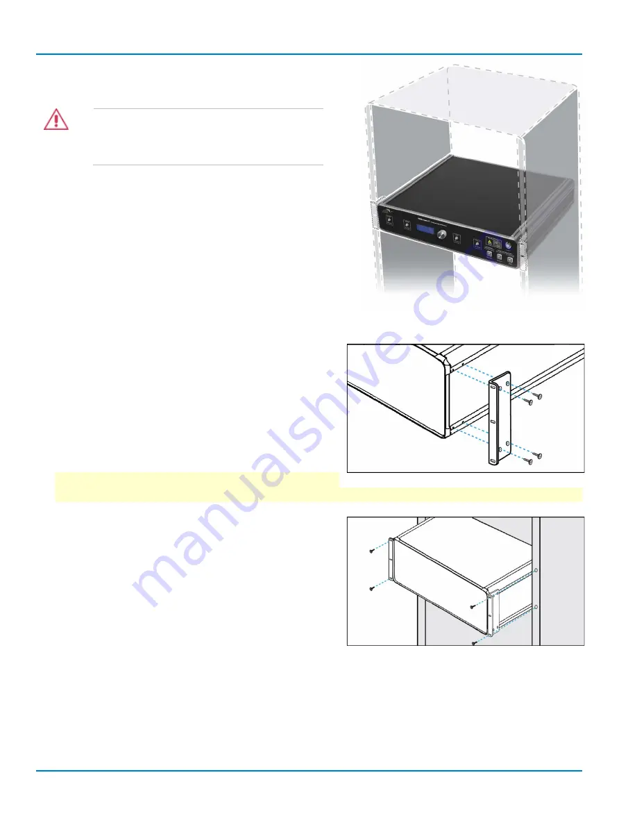
The OMA may also be mounted in a standard 19-inch rack.
CAUTION
Remove all cables attached to the
instruments before attempting to mount the
units within the rack.
Y
OU
P
ROVIDE
•
Optional OMA rackmount kit (IQS-RACKMOUNT) and
optional LabMaster rackmount kits (MCM-Zi-
RACKMOUNT and LM10Zi-ACQMOD-RACKMOUNT).
•
Phillips screwdriver.
•
At least four (4) fasteners to attach the coherent receiver
to the rack. Consult the rack manufacturer’s
documentation to ensure the correct fasteners are used.
S
TEPS
1.
Fasten the mounting brackets (supplied with the
rackmount kit) to the threaded holes located at the
front of both sides of the coherent receiver. Ensure all
four screws of both brackets are securely fastened.
2.
With assistance, position the coherent receiver within
the instrument rack.
IMPORTANT: Ensure sufficient room to mount the
other units around the receiver. This varies depending on the number of acquisition modules.
3.
With the coherent receiver held in position, securely
attach the mounting brackets to the instrument rack
using the fasteners specified by your rack
manufacturer.
4.
Follow the instructions included with the LM 10 Zi
rackmount kit to install the control module and the
acquisition module in the rack.
5.
Go on to make the power, USB, and other cable
connections on the backs of the units before making the RF and optical cable connections on the
front.
Summary of Contents for IQS25
Page 1: ...Operator s Manual Optical Modulation Analyzer ...
Page 2: ......
Page 3: ...Optical Modulation Analyzer Operator s Manual August 2016 ...
Page 86: ...Optical Modulation Analyzer 78 ...
Page 87: ......
Page 88: ...927295 00 Rev A August 2016 ...


