Operator’s Manual
47
Bit Error Rate (BER)
After the input signals are digitally processed, the OMA can create the bit stream that was optically
modulated. This bit-stream can be viewed on the touch screen display grid (as a trace) or saved to a file
for further analysis.
The OMA provides maximum flexibility in terms of how symbols can be mapped to bits. Several common
symbol-to-bit encodings are built in. You can also define how reference symbols are one-to-one mapped
to your own bit encodings. Once symbol-level encoding is done, the next step is to define how data can be
found in individual I and Q channels. Several channel mappings are built in to support typical testing
scenarios.
The recovered bit stream is then used to calculate bit error rate (BER). A range of Pseudo Random Bit
Sequences (PRBS) are provided to support common cases. You can also define custom bit patterns.
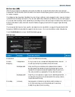
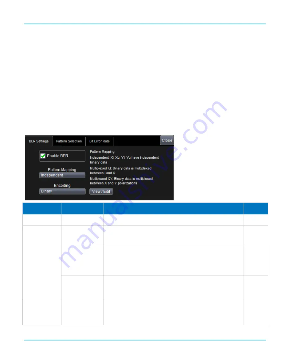
Touch the BER button to access the BER subdialog group.
BER
S
ETTINGS
Control
Selection
Action/Description
Streams
Enable BER
Turns on/off BER functionality.
Pattern
Mapping
Independent
Xi, Xq, Yi and Yq are considered independent data streams.
Yi and Yq will only be available in Dual Pol mode.
4
MultiplexedIQ
XiXq and YiYq are considered two independent streams.
We take bitsPerSymbol bits from Xi followed by the same
number from Xq, back to bitsPerSymbol from Xi and so on.
The same selection is applied to YiYq in dual Pol mode.
2
MultiplexedXY
XiXqYiYq is considered a single stream. bitsPerSymbol bits
are taken from each and concatenated in the same order to
create the final bit array.
1
Encoding
(various)
See Appendix 4: Reference Symbols and Encodings on
p.73. After selecting, touch View/Edit and if necessary
modify the symbol-to-bit encoding.
Summary of Contents for IQS25
Page 1: ...Operator s Manual Optical Modulation Analyzer ...
Page 2: ......
Page 3: ...Optical Modulation Analyzer Operator s Manual August 2016 ...
Page 86: ...Optical Modulation Analyzer 78 ...
Page 87: ......
Page 88: ...927295 00 Rev A August 2016 ...

