background image

GD10-P00 and GD10-PE0 

INFRARED POINT GAS DETECTOR 
OPERATING MANUAL 


22 


850-811250 

Revision 13b


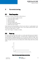
Figure 12: Analog output during specific startup conditions 


5.3


Checking system functions 


Full specification obtained after 30 min. warmup time 

 
The GD10P is factory calibrated  and does not require any adjustments before operation. A check 
prior to putting into service should however consist of: 
1)   Clean the optical  surfaces.  

The detector may have been collecting dirt after being initially  installed. It is thus crucial to 
clean the optical  parts before testing the detector  (refer to  Paragraph  7.1  “Cleaning of 
optical lens/mirror”
). 

2)  Do a gas test. 

To make sure the detector works fine  you should as a minimum do a function check as 
described in paragraph  7.2 “Function test”
Optionally you may do a full calibration test as described in paragraph  7.3  “Calibration 
test”


Startup period can be up to 10 minutes under very specific conditions. This 
corresponds to the temperature adjustment time of the different components. 


If the analog output  of the detector stays at 0.6mA after 10 minutes then the detector 
could have a zero drift issue. This issue can be solved by applying  a “Re-Zero” to 
the detector. This procedure is described in section 7.4. 

Summary of Contents for Everywhereyoulook GD10-P00

Page 1: ...850 811250 Revision 13b GD10 P00 and GD10 PE0 INFRARED POINT GAS DETECTOR OPERATING MANUAL...

Page 2: ...production of all or part of this document in any form is permitted without the written consent of TELEDYNE OLDHAM SIMTRONICS S A S All of the information that is provided in this document is accurate...

Page 3: ...of any of its products UNLESS SUCH PRODUCTS HAVE BEEN SELECTED BY TELEDYNE OLDHAM SIMTRONICS ACCORDING TO THE APPLICATION Ownership clauses The drawings specifications and information herein contain c...

Page 4: ...ase refer to IEC 60079 29 2 standard Warranty Under normal conditions of use and on return to the factory parts and workmanship are guaranteed for 5 years IR sources are guaranteed for 15 years Waste...

Page 5: ...P Weather Protection 14 4 4 GD10P Duct or pipe mounting 15 4 5 GD10PE Fixing 17 4 6 GD10PE Weather protection standalone mounting 17 4 7 GD10PE Duct or pipe mounting 17 4 8 External cable 19 4 9 Elect...

Page 6: ...13b 8 Specific instructions for use in explosive atmospheres and operational safety 35 9 Marking 37 10 Declarations of conformity 39 11 Product coding 43 11 1 GD10P Gas and range code 45 12 Accessori...

Page 7: ...ptible to detection The intensity of this absorption line is however significantly dependent on the molecule under consideration In general the larger the molecule is the greater the absorption streng...

Page 8: ...GD10 P00 and GD10 PE0 INFRARED POINT GAS DETECTOR OPERATING MANUAL 2 850 811250 Revision 13b Suitable for use in SIL 2 and SIL 3 systems...

Page 9: ...nd bulkheads in places such as pump rooms but may also be used as a standalone point detector in places where the properties of the GD10PE is required such as low ppm level detection A weather protect...

Page 10: ...GD10 P00 and GD10 PE0 INFRARED POINT GAS DETECTOR OPERATING MANUAL 4 850 811250 Revision 13b...

Page 11: ...reading Accuracy 3 FS between 0 50 reading 5 FS between 50 100 reading Response time 2 T20 0 8 sec Optional 0 2 sec T50 2 1 sec Optional 0 4 sec T90 5 sec Optional 1 0 sec Start up time Less than 60...

Page 12: ...ntenance HART interface ELECTRICAL Power supply 24 VDC range 18 32 VDC Power consumption Approx 3 5 W Connection 3 wires 0 5mm2 1 5mm2 Cable entry M20 Ex e cable gland ENVIRONNEMENT Storage Temperatur...

Page 13: ...ASTM 316 Weight Approx 2 9 kg 6 4 Lbs Dimensions 264L x 104W x 106H mm 10 4 x 4 1 x 4 2 inches EMC Compliant to EN 50270 and IEC 61326 3 1 7 WARRANTY 5 years full warranty on complete instrument 15 ye...

Page 14: ...GD10 P00 and GD10 PE0 INFRARED POINT GAS DETECTOR OPERATING MANUAL 8 850 811250 Revision 13b...

Page 15: ...0 LEL reading 1 4 LEL 10 20 LEL reading Response time 9 T20 0 8 sec T50 2 1 sec T90 5 sec Start up time Less than 60 sec10 full specification obtained after 30 min warmup time 8 The detector is intend...

Page 16: ...k 4 20 mA Maintenance HART interface ELECTRICAL Power supply 24 V DC range18 32 V DC Power consumption Approx 3 5 W Connection 3 wires 0 5mm2 1 5mm2 Cable entry M20 Ex e cable gland ENVIRONNEMENT Stor...

Page 17: ...Stainless steel SIS2343 ASTM 316 Weight Approx 6 5 kg Dimensions 805L x 104W x 106H mm EMC Compliant to EN 50270 and IEC 61326 3 1 14 WARRANTY 5 years full warranty on complete instrument 15 years war...

Page 18: ...GD10 P00 and GD10 PE0 INFRARED POINT GAS DETECTOR OPERATING MANUAL 12 850 811250 Revision 13b...

Page 19: ...here maintenance i e cleaning of the optics is easily performed The detector may be mounted in areas where no oxygen is present The detector may be mounted in areas with strong airflow The detector ca...

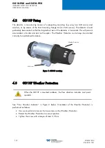
Page 20: ...l prevent accumulation of water and dust on the optics The Weather Protection must always be oriented correctly for optimal performance Figure 1 GD10P mounting 4 3 GD10P Weather Protection When the GD...

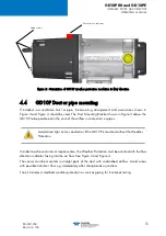
Page 21: ...d in the core of the airflow in wide ducts or pipes Avoid direct light on lens and mirror if the GD10P is mounted without the Weather Protection In order to achieve minimum response time the Weather P...

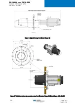
Page 22: ...INFRARED POINT GAS DETECTOR OPERATING MANUAL 16 850 811250 Revision 13b Figure 3 Exploded view Duct Mount Flange Kit Figure 4 Ventilation duct or pipe mounting using Duct Mounting Flange Kit Refer to...

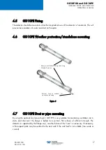
Page 23: ...D10PE Duct or pipe mounting By using the optional duct mounting kit GD10PE is very suitable for monitoring ventilation air in ducts and channels The flange is bolted to a vertical flat surface of suff...

Page 24: ...on is at some distance behind the first filter or grille when used for forced flow air intakes You may also just bolt the detector as stand alone with the nose bracket support but this is not advisabl...

Page 25: ...insulated ducts it is necessary to remove some insulation Figure 9 4 8 External cable The cable type must be chosen in accordance with applicable regulations The table below indicates maximum cable l...

Page 26: ...nt The unused entry is blanked with an Ex e cover The detector housing must be connected to local ground via the external earth point The wire should be minimum 4 mm2 8 AWG and as short as possible Th...

Page 27: ...Make sure that the flat support surface is clean properly greased and that it does not show any visible scratches or knocks Please refer to Chapter 4 Installation for details 5 2 Power up Ensure that...

Page 28: ...lean the optical parts before testing the detector refer to Paragraph 7 1 Cleaning of optical lens mirror 2 Do a gas test To make sure the detector works fine you should as a minimum do a function che...

Page 29: ...uction 1 mA No detection Early Dirty Optics Warning 55 signal reduction 2 mA Detector will still output gas concentration if it is greater than 7 of range FS 10 of range 0 6 mA Default 0 of range 4 mA...

Page 30: ...org registered products product name GD10P The loading of the DD onto a specific communicator must be done according to the relevant user guide for that communicator The loss of HART communication is...

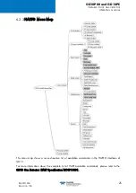
Page 31: ...250 Revision 13b 25 6 2 3HART Menu Map This menu map shows a non exhaustive list of available commands in the HART interface of GD10 For more information about the complete list of HART available comm...

Page 32: ...ated the operator is navigated to one or several data input screens where detailed data can be entered or predefined options selected Detailed navigation between the commands is not explained as this...

Page 33: ...tection range After a reconfiguration it is recommended to restart the detector and verify the new settings by simulating different alarm warning states A current meter may be used to read the level a...

Page 34: ...outside a specific temperature range 16 C 26 C If the Zero level is not improved after the zeroing the reason is that the zero drift is over the allowed limit for field trimming 6 2 4 11 GD10 Loop Te...

Page 35: ...ce is clean For difficult contaminants the mirror and lens can be cleaned with an equal part mixture of isopropyl alcohol and water Do not perform any testing of the detector before this solution has...

Page 36: ...t is required by regulations or in cases where you need to verify system performance during commissioning or similar thorough testing The GD10P PE detectors have a fixed calibration from the factory A...

Page 37: ...hown in the drawing The test gas should be the same as the target gas Humidity of the test gas is 0 100 RH uncondensed At 40 C 50 RH means volume H2O 3 5 Gas flow should be approximately 1 liter minut...

Page 38: ...GD10 P00 and GD10 PE0 INFRARED POINT GAS DETECTOR OPERATING MANUAL 32 850 811250 Revision 13b Do not forget to remove the Gas Test Socket when calibration test is over...

Page 39: ...ctors should normally be returned to the factory for service An alternative is to do this re zeroing on site with a dedicated hand held terminal or HART communicator Note that on site does not mean in...

Page 40: ...ginal value the output signal will go down to Early Dirty Optics see section 6 1 for further details If the IR transmission is further attenuated the output signal will go down to Dirty Optics fault I...

Page 41: ...cessories plugs adaptors etc shall be flameproof certified db or eb for use in gas atmospheres and Ingress Protection will be greater or equal to IP 66 They shall be of M20x1 5 type according to ISO96...

Page 42: ...ED POINT GAS DETECTOR OPERATING MANUAL 36 850 811250 Revision 13b 8 1 1 6 Functional safety certification For all information related to the safety function of the GD10P PE gas detectors please refer...

Page 43: ...TING MANUAL 850 811250 Revision 13b 37 9 Marking The GD10P PE identification labels are shown in the figures below as example ATEX IECEx INMETRO MED markings combustible gases version ATEX IECEx INMET...

Page 44: ...GD10 P00 and GD10 PE0 INFRARED POINT GAS DETECTOR OPERATING MANUAL 38 850 811250 Revision 13b CSA marking combustible gases version...

Page 45: ...GD10P00 and GD10PE INFRARED POINT GAS DETECTOR OPERATING MANUAL 850 811250 Revision 13b 39 10 Declarations of conformity...

Page 46: ...GD10 P00 and GD10 PE0 INFRARED POINT GAS DETECTOR OPERATING MANUAL 40 850 811250 Revision 13b...

Page 47: ...GD10P00 and GD10PE INFRARED POINT GAS DETECTOR OPERATING MANUAL 850 811250 Revision 13b 41...

Page 48: ...GD10 P00 and GD10 PE0 INFRARED POINT GAS DETECTOR OPERATING MANUAL 42 850 811250 Revision 13b...

Page 49: ...Vol 17EG Methane CH4 100 LEL 2 4 4 Vol 18BG Methane Biogas CH4 CO2 100 Vol 23AN Carbon dioxide CO2 10000 ppm 23BH Carbon dioxide CO2 3 Vol 24BC Carbon dioxide Methane immune CO2 5 Vol 24BG Carbon dio...

Page 50: ...calibration a selection of most used variants 03AM Ethylene C2H4 5000 ppm 17DE Methane CH4 20 LEL 1 B Configuration 0 Fixed default value Approval 0 None B CSA X ATEX IECEx INMETRO Interface H 4 20mA...

Page 51: ...05DG Ethanol C2H5OH 3 3 05EG Ethanol C2H5OH 3 1 07DG Propene C3H6 2 0 08DG Acetone C3H6O 2 6 09DG Propane C3H8 2 2 09EG Propane C3H8 1 7 11DG Pentane C5H12 1 4 12DG n Hexane C6H14 1 1 13DG Benzene C6H...

Page 52: ...GD10 P00 and GD10 PE0 INFRARED POINT GAS DETECTOR OPERATING MANUAL 46 850 811250 Revision 13b...

Page 53: ...38 Mosquito Set Assy GD10P Insect protection in stainless steel mesh Slides on the outside of the standard weather protection 499 813397 Sun shade Assy GD10P for horizontal mounting protects from dire...

Page 54: ...15733 GD10PE Duct Mounting Flange 499 815271 12 3 Spares Spare Parts Description Part Number Weather Protection Kit GD10P 499 810913 Cap cover for the gas test nozzle GD10P and GD10PE 599 904176 Rear...

Page 55: ...0 2 years in clean atmosphere 499 815712 100 RH uncondensed 1013 hPa 10 2 years in clean atmosphere 599 816841 100 RH uncondensed 1013 hPa 10 2 years in clean atmosphere 499 816867 100 RH uncondensed...

Page 56: ...GD10 P00 and GD10 PE0 INFRARED POINT GAS DETECTOR OPERATING MANUAL 50 850 811250 Revision 13b...

Page 57: ...GD10P00 and GD10PE INFRARED POINT GAS DETECTOR OPERATING MANUAL 850 811250 Revision 13b 51...

Page 58: ...GD10 P00 and GD10 PE0 INFRARED POINT GAS DETECTOR OPERATING MANUAL 52 850 811250 Revision 13b...

Page 59: ...GD10P00 and GD10PE INFRARED POINT GAS DETECTOR OPERATING MANUAL 850 811250 Revision 13b 53...

Page 60: ...served 850 811250 Revision 13b June 2021 AMERICAS 14880 Skinner Rd CYPRESS TX 77429 USA Tel 1 713 559 9200 EMEA Rue Orfila Z I Est CS 20417 62027 ARRAS Cedex FRANCE Tel 33 0 3 21 60 80 80 ASIA PACIFIC...

Reviews: