Operation
3000ZA
Teledyne Analytical Instruments
44
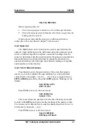
Press
Enter
to enter the span value into the system and begin the
span calibration.
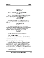
Once the span has begun, the microprocessor samples the output at
a predetermined rate. It calculates the difference between successive
samplings and displays this difference as a Slope on the screen. It takes
several seconds for the first Slope value to display. Slope indicates the
rate of change of the Span reading. It is a sensitive indicator of stability.
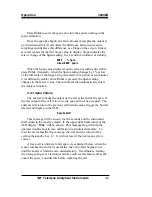
#### % Span
Slope=#### ppm/s
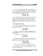
When the Span value displayed on the screen is sufficiently stable,
press
Enter
. (Generally, when the Span reading changes by 1% or less
of the full scale of the range being calibrated, for a period of ten minutes
it is sufficiently stable.) Once
Enter
is pressed, the Span reading
changes to the correct value. The instrument then automatically enters
the Analyze function.
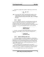
4.4.3 Span Failure
The analyzer checks the output of the cell at the end of the span. If
the raw output of the cell is too low, the span will not be accepted. The
analyzer will return to the previous calibration values, trigger the System
Alarm, and display in the VFD:
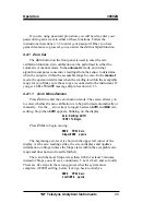
Span Failed!!
This message will be shown for five seconds and the instrument
shall return to the Analyze mode. In the upper right hand corner of the
VFD display “
FCAL
” will be shown. This message flag will help the
operator troubleshoot in case calibration was initiated remotely. To
reset the alarm and the flag message, the unit must be turned off by
cycling the standby key . It will not reset if the next span cycle is
correct.
A trace cell is unlikely to fail span. As explained before, when the
sensor reaches the end of its useful life, the zero offset begins to rise
until the analyzer finds the zero unsatisfactory. Nevertheless, feeding
the wrong span gas or electronics failure could set this feature off at the
end of the span. Consider this before replacing the cell.
Summary of Contents for 3000ZA
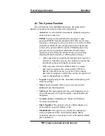
Page 24: ...Operational Theory 3000ZA Teledyne Analytical Instruments 12 Figure 2 3 Component Location...
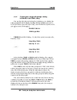
Page 63: ...Trace Oxygen Analyzer Operation Teledyne Analytical Instruments 51...
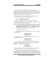
Page 77: ...Trace Oxygen Analyzer Appendix Teledyne Analytical Instruments 1 SCFH 0 476 SLPM...
Page 81: ...Trace Oxygen Analyzer Index Teledyne Analytical Instruments...


