Echotrac MKIII Operator's Manual 4.06
Page 26 of 48
January 21, 2019
In the dual frequency MKIII, two DRAFT and INDEX values are required in order to compensate for possible
separate locations of the high and low frequency transducers. As one would imagine,
DRAFT HI
and
INDEX HI
compensate for the high frequency channel and
DRAFTLO
and
INDEXLO
compensate for the low frequency
channel. Depth is computed according to the general formula shown below:
d = ½ (v * t) - k + d
r
d
= depth from water's surface
v
= average speed of sound in the water column
t
= measured elapsed time of signal travel from transducer to seabed and back to the transducer
k
= system index constant
d
r
= difference from referenced water surface to transducer (draft)
5.2.3.5
Hi Channel and Low Channel
Select which channel (High or Low) to calibrate using this parameter during calibration. Since only one channel or
frequency can be calibrated at a time, and the Channel parameter resides in the System menu, an easier method
of selecting which Channel to transmit had to be devised. The addition of another Channel parameter in the
Calibration menu eliminates having to switch between menus during calibration. The Channel parameter in the
Calibration menu is valid only during calibration.
5.2.4
Chart Menu
5.2.4.1
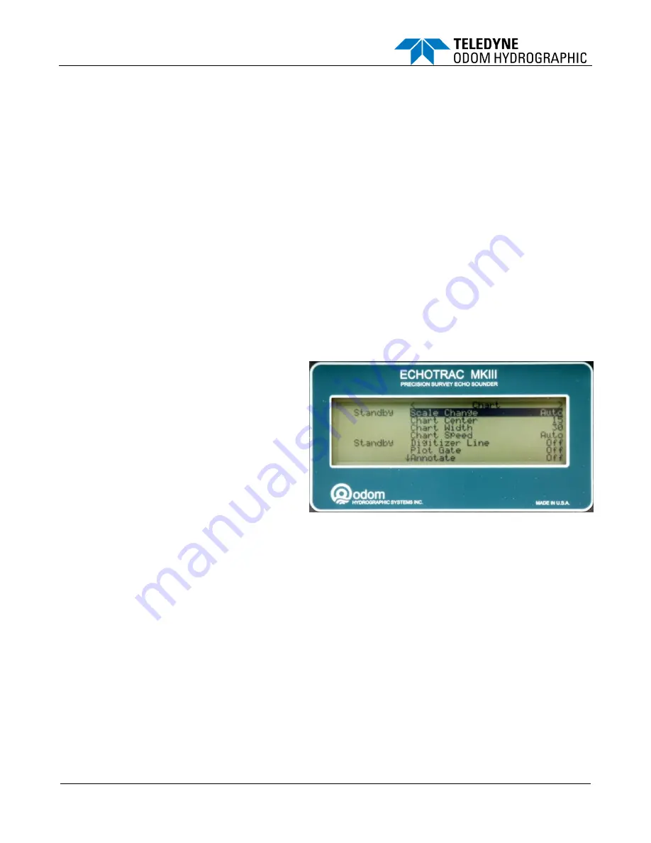
Scale Change
In
Auto,
the digitizer is in an automatic scale change
(auto phasing) mode. Auto is selected when the
operator wants the MKIII to acquire the bottom and
automatically adjust the printed scale so that bottom
returns always remain visible on the chart. If the
digitized depth approaches either scale limit in
Auto
,
a new scale center is computed which will place the
bottom (digitized depth) at a point 10%, 20%, or 30%
of the way into the chart display area. This 'overlap' is
necessary to prevent redundant scale changes in
areas where the bottom varies near either edge of the
chart.
Auto 20%
is the default and desirable in most
bottom conditions.
Auto 10%
would be selected where steep banks or drop-offs cause rapid scale changes and use of
as much of the chart as possible is desired. A 30% overlap would be used where deep sub-bottom data is being
produced and one would wish to have the Scale change before possibly cutting off any sub-bottom data at the end of
scale. Auto Scale changes are noted on the chart by the printing of solid vertical black lines.
In
Manual,
the digitizer is constrained by the
Chart Width
and
End of Chart
values regardless of depth. It is
therefore quite possible in Manual mode to lose both digital and printed return data altogether, since the depth
can easily change to the point where the bottom will be out of range of the manual scale limits
.
Manual is most
often used to eliminate unwanted automatic scale changes that can occur in very noisy conditions and where the
limits of bottom depth changes are well known.
5.2.4.2
End of Chart
As the name implies, the
End of Chart
parameter refers to the depth value at the end or bottom of the printed
record. When the Scale Change parameter is in AUTO mode, the End of Chart value is recomputed each time the
digitized depth approaches either the upper of lower scale limit.
End of Chart
is used to compute the echo travel time and thereby sets the auto ping rate of the unit.
Summary of Contents for Echotrac MKIII
Page 4: ......


