background image

Foxy

®

 R1 and Foxy

®

 R2 Fraction Collectors

Section 4  Serial Command Control

4-16

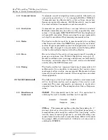
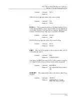
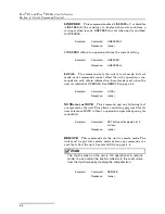
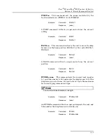
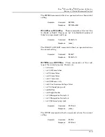
UPLOAD=n

This command chooses which program line (

n=0

to 

71

) is to be sent next.

UPLOAD=–1

This command responds with the command

strings for the entire current program immediately.

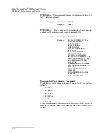
Unsupported Programming Commands

The following serial commands are not supported by the fraction
collector. 

ESTATE=n

ETIME=n

ETYPE=n

EVENT=n

LIST

PTYPE

These commands were available for earlier fraction collector
models. Do not use them with the Foxy R1 and R2 fraction col-
lectors.

Example:

Command:

UPLOAD=0

Response:

(none)

Example:

Command:

UPLOAD=–1

Response:

NOTE=PROGRAM 3PTYPE=4
LAST=144PATERN=1
FTYPE=1FSIZE=1
DELAY=0RANGE=1
THRESHOLD=0
WIDTH=11NONPEAK=3
RESTART=2
WINDOW=1; WSTART=0;
WEND=60WINDOW=2;
WSTART=120;WEND=240
NOTE=Config: Pump off=0, Only 
rack=11NOTE=Pattern=3, Peak 
det. =5, Motor=5NOTE=Cal: 
0mV=32768, 
1V=58982,NOTE=100mV=58982, 
10mV=35389,NOTE=Time=749, 
VREF=500, 
Bklash=0NOTE=FLLR=128, 
FLFB=128, 
FRLR=128NOTE=FRFB=128, 
BLLR=128, 
BLFB=128NOTE=END

Summary of Contents for Foxy R1

Page 1: ...Foxy R1 and Foxy R2 Fraction Collectors Part 69 2133 667 Copyright 2008 All rights reserved Teledyne Isco Revision K April 2020 Foxy R2 Foxy R1 ...

Page 2: ......

Page 3: ... service please follow the shipping instructions provided by technical support including the use of the Return Material Authorization RMA specified Be sure to include a note describing the malfunction This will aid in the prompt repair and return of the equipment Teledyne Isco is continually improving its products and reserves the right to change product specifications replacement parts schematics...

Page 4: ......

Page 5: ...Tray Drain Connection 2 9 2 3 Rack Installation 2 10 2 4 Diverter Valve Adjustment 2 12 2 5 Installation Qualification Checklist 2 13 Section 3 Programming 3 1 Main Menu 3 2 3 2 Configuration Settings 3 3 3 2 1 Rack Settings 3 3 3 2 2 RS 232 Serial Settings 3 5 3 2 3 TCP IP Settings 3 6 3 2 4 Inject Options 3 6 3 2 5 Pump Control Settings 3 9 3 2 6 Analog Peak Settings 3 9 3 2 7 Fraction Collector...

Page 6: ... 4 5 3 Programming Commands 4 9 4 5 4 Problem Responses 4 17 Section 5 Maintenance 5 1 Introduction 5 1 5 2 Maintenance 5 1 5 2 1 Tubing Inspection 5 1 5 2 2 Collection Rack and Drip Tray Cleaning 5 2 5 2 3 Exterior Cleaning 5 2 5 2 4 Fluid Path Cleaning 5 2 5 2 5 Drop Counter Cleaning 5 3 5 3 Service 5 4 5 4 Instrument Returns 5 4 5 4 1 How to Ship Returns 5 4 Appendix A Icon Glossary and Menu Ch...

Page 7: ...14 Diverter Valve adjusted with 1 2 inch or 1 cm clearance 2 12 3 1 Main Menu 3 2 3 2 Configuration Tools Menu 3 3 3 3 Rack options menu 3 3 3 4 Inject options timing diagram 3 7 3 5 Timed options timing diagram 3 7 3 6 Overlay Next and Skip options diagram 3 8 3 7 Method Settings Menu 3 10 3 8 Method Selection Menu 3 10 3 9 Rename Method display 3 11 3 10 Drop Counts display 3 11 3 11 Time Interv...

Page 8: ...Ethernet Connector Pins 1 8 1 5 Pump Connector Pins 1 9 1 6 Detector Connector Pins 1 9 1 7 RS 232 Serial Communication Connector Pins 1 10 1 8 Non Isco Pump Cable P N 69 2134 170 1 11 1 9 Non Isco Detector Cable P N 69 2134 171 1 11 5 1 Installation Qualification Checklist 2 13 A 1 Touch screen display icons A 1 ...

Page 9: ...the instrument may be impaired WARNING If this system uses flammable organic solvents Teledyne Isco recommends that you place this system in a well ventilated environment designed for these types of materials This environment should be constructed in accordance with federal state and local regulations It should also comply with your organization s plan concerning chemical and hygiene mishaps In al...

Page 10: ...ial hazard which if not avoided may result in minor or moderate injury This category can also warn you of unsafe practices or conditions that may cause property damage WARNING Warnings identify a potentially hazardous condition which if not avoided could result in death or serious injury DANGER DANGER limited to the most extreme situations to identify an imminent hazard which if not avoided will r...

Page 11: ...t Symboles de sécurité Ce symbole signale l existence d instructions importantes relatives au produit dans ce manuel Ce symbole signale la présence d un danger d électocution Warnungen und Vorsichtshinweise Das Ausrufezeichen in Dreieck ist ein Warnzeichen das Sie darauf aufmerksam macht daß wichtige Anleitungen zu diesem Handbuch gehören Der gepfeilte Blitz im Dreieck ist ein Warnzeichen das Sei ...

Page 12: ...Foxy R1 and Foxy R2 Fraction Collectors Safety xii ...

Page 13: ... col lectors have the ability to divide the liquid into multiple col lection vessels switching vessels on time drops volume peaks or a combination of these parameters Collection vessels can be test tubes vials mini wells bottles and funnels The symbolic touch screen display simplifies set up for a variety of collection routines Figure 1 1 Foxy R1 left and Foxy R2 right fraction collectors ...

Page 14: ...ht absorbing compounds in chromatographic eluate Signals may also represent other measurable liquid properties such as visible light absorbance fluorescence pH or any parameter with an analog output signal Tube advances at the leading and lagging edges of the peak isolate peak fluids from non peak fluids com monly called peak cutting These peak collection modes are Threshold Peak Detection The fra...

Page 15: ...llowing racks are available These racks are chemically resistant made from stainless steel and polypropylene The racks accept standard sized user sup plied tubes vials and microplates of any material When in place these racks are electrically grounded This safety feature dissipates electrostatic charges when collecting organic solvents at high flow rates 60 2137 150 One rack for 13 mm diameter tub...

Page 16: ...ter valve assembly either depos its fluids into the vessel or out to a user supplied waste container The standard diverter valve assembly includes the drop for mer counter 3 The height adjustment knob allows the user to set drop for mer counter outlet at safe yet minimal distance above the collection tubes or funnels 4 The fraction collector arm moves along the Y axis to position the arm over the ...

Page 17: ...Foxy R1 and Foxy R2 Fraction Collectors Section 1 Introduction 1 5 Figure 1 2 Fraction collector features ...

Page 18: ...s 60 rack 50 mL centrifuge tubes 36 rack 28 mm diameter scintillation vials 36 rack 96 well microplates R1 rack holds 2 plates R2 rack holds 6 plates 480 mL bottlesb Funnel racks for fractions larger than 480 mL Maximum Tube Height Foxy R1 160 mm Foxy R2 196 mm Foxy R2 High Flow 180 mm Maximum Flow Rate Foxy R1 68 3870 012 Standard flow rate of 25 mL min through 1 16 inch I D tubing Optional acces...

Page 19: ...ctc tube advancec analog peak voltaged Outputs Pump pausee tube change eventf Wetted Materials Valve PEEK and Perfluoroelastomer FFKM Supplied ferrules ETFE Supplied valve tubing PTFE Supplied drain tubing Vinyl Typical Applications Prep HPLC peptide protein purification soil extraction density gradient fractionation Electrical Safety per EN 61010 1 Second Edition Maximum Altitude 2000 meters Poll...

Page 20: ...ctor Connector Table 1 6 5 RS 232 Serial Connector Table 1 7 6 AC Mains Power Mains power must meet the voltage fre quency and amperage requirements listed on the serial number label Mains power fluctuations must not exceed 10 of the nominal supply voltage The mains power cord is the disconnect device Table 1 4 Ethernet Connector Pins Connector Pin Type Description 1 Output Input TX RX auto MDI MD...

Page 21: ... low 30 ms minimum 5 VDC maximum b Output is open collector active low 15 VDC 100 mA maximum Table 1 6 Detector Connector Pins Connector Pin Type Description 1 Common Analog common for use with pin 8 2 Input Ext peaka 3 Not used 4 Output Event pulse delivered at tube changeb 5 Input Inject starts an inject cycle1a 6 Input Tube Advance1a 7 Common Circuit common 8 Input Analog detector signal used f...

Page 22: ...as the UA 6 order accessory cable 69 2134 173 This cable carries the analog peak detector signal as well as the tube advance event pulse external peak and inject signals 1 6 2 Cable for non Isco Pumps A cable is available to connect the fraction collector to a non Isco pump Part number 69 2134 170 is a six foot long cable with one end terminated as a 6 pin mini DIN connector The other end is strip...

Page 23: ...BRN Output Pump pause stops pump between tubes and at end of run 3 RED Output Valve output control signal for optional high flow diverter valve 4 ORN Common Circuit common 5 YEL Output 24 VDC Output power for optional high flow diverter valve 6 GRN Not used K N A Shield Earth ground Table 1 9 Non Isco Detector Cable P N 69 2134 171 Connector Pin Color Type Description 1 BLK Common Analog common fo...

Page 24: ...Foxy R1 and Foxy R2 Fraction Collectors Section 1 Introduction 1 12 ...

Page 25: ...tional accessories ordered with the fraction collector might be shipped in a separate carton Inspect the fraction collector for damage that might have occurred during shipping Notify the shipping carrier immedi ately if you find any damage 2 1 Preliminary Checkout Before using the fraction collector you should perform a prelim inary checkout to ensure it functions properly This includes testing el...

Page 26: ...ction collector upright on a level surface 2 Remove any wrapping or packing materials from the frac tion collector The arm and diverter valve assembly should move freely 3 Loosen the diverter valve thumb screw s and raise the diverter valve to its highest position Figure 2 1 Tighten the thumb screw s to secure the diverter valve 4 Connect the fraction collector to AC mains power using the supplied...

Page 27: ...eliminary checkout procedure 6 Touch the Folder icon twice to open a list of collection methods Method A should be selected If not touch the up or down arrows to highlight Method A Figure 2 3 Method Select screen 7 Touch the Enter icon to accept Method A and return to the screen at which you can edit the method settings Method A Method B 16mmTube Method D DefaultE DefaultF DefaultG DefaultH ...

Page 28: ...o seconds 11 Touch the Enter icon twice to save the setting and return to the main menu Figure 2 5 Time based Fractions screen 12 Touch the Play icon to start operation The arm and drop former will move to the first tube position and then advance to the next tube every two seconds Allow the drop former to advance through at least 20 tubes to ensure that the arm freely moves through the X and Y axe...

Page 29: ...he standard diverter valve Refer to section 2 2 2 for instructions on the high flow rate valve connections Both valves are shown in Figure 2 1 on page 2 2 2 2 1 Standard Diverter Valve Connections Note The In and Waste connections use special headless fittings The position of the ports prevent the use of standard Upchurch fittings Figure 2 6 shows the standard diverter valve ports Figure 2 6 Diver...

Page 30: ...ng should be observed the yellow ferrule should be flush and perpendicular with the end of the tubing the metal lock ring should be compressed over the ferrule without any gaps all pieces should be correctly aligned and free from any deformation If not fully swaged reinsert the headless nut into the port and tighten further Remove the headless nut and inspect again using the criteria above 8 Repea...

Page 31: ... valve through the full range of motion Ensure the In and Waste tubing do not obstruct the movement If necessary secure the tubing using the adhesive backed clips from the accessory package 2 2 2 High Flow Diverter Valve Connections Figure 2 9 shows the high flow diverter valve ports To connect the fluid lines 1 Place the unit in Standby by touching the Standby ON icon 2 Remove any installed racks...

Page 32: ...tes the electrostatic charge If handling organic solvents at high flow rates do not substitute the conductive tubing Note Cut the tubing with a tubing cutter to ensure that the end is cut cleanly and free from any deformation 4 Prepare one end of each tubing piece as shown in Figure 2 10 Figure 2 10 Tubing preparation high flow 5 Using two wrenches connect the In and Waste tubing to the valve usin...

Page 33: ...nsure the In and Waste tubing do not obstruct the movement If necessary secure the tubing using the adhesive backed clips from the accessory package Figure 2 11 Connections to high flow diverter valve 2 2 3 Drip Tray Drain Connection Connect the 5 16 inch I D clear vinyl tubing to the drip tray drain and route it to a suitable waste container CAUTION Connect tubing to the drip tray drain when coll...

Page 34: ...ors will detect the installed rack using RFID technology and configure the operation settings for the detected rack and tube size To install a rack 1 Select the rack and insert the collection tubes Note Collection tube height must not exceed 150 mm for use with the Foxy R1 fraction collector Tube height must not exceed 180 mm for use with the Foxy R2 fraction collector 2 Ensure that the tops of th...

Page 35: ...e If this applies to your application racks must be installed correctly on the guide pins to ground the collection vessels An electrical ground is necessary to dissipate electro static charges that may build while collecting fluids such as organic solvents 5 Verify that the spring loaded post on the left side of the rack is touching the guide pin Figure 2 13 Figure 2 13 Rack installed with ground ...

Page 36: ...y 2 Move the arm and drop former to a convenient location over the installed collection rack 3 While holding the diverter valve with one hand loosen the thumb screw s with the other Do not remove the thumb screw s 4 Lower the diverter valve so that the drop former is close to the top of the collection tubes Figure 2 14 Generally a 1 2 inch or 1 cm space between the drop former and the top of the t...

Page 37: ...tion Installer Initials Operator Initials 2 1 Preliminary Checkout 2 2 1 2 2 2 Standard Diverter Valve Connections or High Flow Diverter Valve Connections 2 2 3 Drip Tray Drain Connection 2 3 Rack Installation 2 4 Diverter Valve Adjustment Certification of Section 2 Completion Installer Name print Installer Signature Date Operator Name print Operator Signature Date Comments ...

Page 38: ...Foxy R1 and Foxy R2 Fraction Collectors Section 2 Preparation for Use 2 14 ...

Page 39: ...ommand Control The fraction collector in these applications is interfaced with an external controlling device through the RS 232 Serial or Ethernet connectors as well as the optional pump and detector inputs Note The display shows a computer icon if the system is under remote control Refer to Section 4 for serial control programming instructions and to the docu mentation supplied with the controll...

Page 40: ... of the fraction collector after you touch the Play icon These settings define tube change intervals peak cutting time windows etc Up to eight different methods can be defined one of which is always current For more details see Section 3 3 The other Main Menu icons are briefly discussed below Touch the Diverter Valve Position icons to toggle the position of the diverter valve When the arrow points...

Page 41: ... the settings whenever the configuration changes Sections 3 2 1 through 3 2 7 provide details for each of the Configuration Tools menu options Figure 3 2 Configuration Tools Menu 3 2 1 Rack Settings Touch the rack icon to view the Rack options menu Figure 3 3 From this menu you can view or change the type of rack set the collection pattern and speed and calibrate the drop former position over the ...

Page 42: ...ewer tubes than the capacity of the rack touch the Number of Tubes icon Use the Arrow icons to specify the last tube in the rack then touch the Enter icon to accept the value 4 Touch the Enter icon to save the selection and return to the Rack Options menu Note Touching the Enter icon again will return the fraction collector to the Configuration Tools menu Touching it once more will display the Mai...

Page 43: ...ystem 3 Touch the Calibrate icon to access the calibration options 4 Touch the First Tube icon to move the drop former over the front and left most tube in the rack 5 Touch the Arrow buttons to incrementally position the drop former over the center of the collection vessel opening Note The white diverter valve housing has a arrow on the face to indicate the center of the drop former outlet This ca...

Page 44: ...Left and Right Arrow icons d Touch the Enter icon to save the setting and return to the previous display Note Should you need assistance with determining the correct static IP address and IP Mask values contact your IT department Note The view only MAC address is unique to each fraction collector and cannot be changed 3 2 4 Inject Options Inject options also known as Restart options control the op...

Page 45: ...ions This process repeats until the end of the run Timed The timed options do not rely on external signals nor does it pause for injections When using one of the timed options the fraction collector assumes that each of the multiple sample injections are performed at fixed time intervals For example the chemist injects a sample and touches the Play icon to start the run Figure 3 5 Thereafter anoth...

Page 46: ...ter icon to save the setting and return to the previous display Overlay Next or Skip The Inject or Timed restart options are combined with a col lection tube option Overlay Next or Skip These options are illustrated in Figure 3 6 Overlay If you select the overlay option the fraction collector moves the drop former back to the original tube position That is at every restart the drop former returns ...

Page 47: ...nal pump will continue to operate during tube changes The icon with the 0 indicates that the fraction collector will send a pause signal from pin 2 Touch the icon to toggle the state 3 2 6 Analog Peak Settings The fraction collector can receive an analog peak signal from an external detector The fraction collector receives this signal at pin 8 of the Detector connector When using this feature set ...

Page 48: ... list of methods highlights the current method name Figure 3 8 To select a different method use the Up and Down Arrows to highlight the desired method Touch the Enter icon to accept the new method and return to the Method Settings display Figure 3 8 Method Selection Menu You can also rename the methods After highlighting a method touch the Folder icon The fraction collector displays a text editing...

Page 49: ...orm collection tube vol umes even when the delivered flow rate varies However if the fluid viscosity varies while running a gradient the collection tube volumes may vary Note The drop count option assumes that the flow rate is slow enough to produce drops instead of a stream of liquid Conse quently drop counting is not supported by the Foxy R2 High Flow fraction collector To create fractions based...

Page 50: ...ment the numbers the Left and Right Arrows move the cursor position 6 Touch the Enter icon to return to the Methods Settings menu About Flow Delays A Flow Delay synchronizes the tube changes with sample flow to make precise peak cutting possible The flow delay time is the time required for a fraction to travel from your detector to the fraction collector s drop former The delay depends on the flow...

Page 51: ...inutes and seconds 2 Ensure that the fraction volume setting is active as indi cated by the Volume Select icon That is the tube should be highlighted with a border If not touch the icon to toggle the setting 3 Enter the fraction volume as hours minutes and seconds using the arrow icons The Up and Down Arrows incre ment or decrement the numbers the Left and Right Arrows move the cursor position 4 T...

Page 52: ...option 1 Touch the Volume icon to open the settings display Figure 3 12 Figure 3 12 Volume display Use this display to set the fraction volume and delay volume both expressed as pump counts 2 Ensure that the fraction volume setting is active as indi cated by the Volume Select icon That is the tube should be highlighted with a border If not touch the icon to toggle the setting 3 Enter the fraction ...

Page 53: ...f the of the pump count vol ume 6 Touch the Enter icon to return to the Methods Settings menu 3 3 5 Threshold Detection Threshold detection isolates the most concentrated portion of peaks The threshold is set as a percentage of the maximum input signal When the input signal rises above this threshold value the fraction collector performs a tube advance to isolate the peak An example of threshold p...

Page 54: ...uids will be diverted to waste The icon that is shaded below the threshold indicates that non peak fluids will be collected in tubes Touch the icon to toggle the selection 4 Threshold peak detection can be used alone or combined with slope detection You can control these options using the icon in the upper right corner of the display The None icon left indicates that Threshold detection is Off The...

Page 55: ...dicates the end of a peak The internal slope detection algorithms are effective in isolating multiple shouldered peaks peaks that do not return to the baseline before the next peak occurs The peak width option is useful to eliminate false peaks that can result from a rising or noisy baseline An example of Peak Width detection and collection is shown in Figure 3 15 The peaks on the analog signal ar...

Page 56: ... the percentage shows what the fraction collector will do with non peak fluids The icon that is clear below the threshold indicates that non peak fluids will be diverted to waste The icon that is shaded below the threshold indicates that non peak fluids will be collected in tubes Touch the icon to toggle the selection 4 Peak width detection can be used alone or combined with threshold detection Yo...

Page 57: ...ion icons allow you to combine peak detection methods If you have programmed both peak detection methods this setting will determine whether both or any one of the peak conditions must be true Refer to the diagrams below for a comparison Intersection AND The fraction collector cuts peaks 2 and 3 where the input signal exceeds the threshold value and a slope is determined by the peak width setting ...

Page 58: ...nterest 1 to waste until the start of Time Window 1 The fraction collector continues to divert fluid to waste until it detects Peak 2 at which time it begins collection until the end of the peak Peak 3 although it exceeds the threshold is diverted to waste because it does not occur in a time window Without a detected peak at the start of Time Window 2 fluid is still diverted to waste until the sta...

Page 59: ...he time from the start of the run press ing the Play icon 4 Touch the Start End icon to advance to the end of Time Window 1 5 Enter the Time Window 1 end time using the Arrow icons This value is the time from the start of the run 6 If you are using only one time window touch the Enter icon to save the settings and return to the Method Settings menu To use more than one time window touch the Start ...

Page 60: ...Foxy R1 and Foxy R2 Fraction Collectors Section 3 Programming 3 22 ...

Page 61: ...ation Information Communication with the fraction collector can be established through either Ethernet port These connections use a Category 5 or higher cable The fraction collector will automatically detect straight and cross over cables and configure the communi cation accordingly Refer to Section 3 to configure the TCP IP settings of the fraction collector The fraction collector uses port 23 fo...

Page 62: ...sage responses See Problem Responses on page 4 17 Hardware related errors warnings and failures are indicated by the display and audio output of the unit and can be detected serially using the STATUS command 4 4 6 Timing The fraction collector s response time to most commands is 50 milliseconds One exception is commands that require some mechanical action such as arm movement Mechanical actions no...

Page 63: ...nt setting HELP The unit will respond to this command with a list of valid command names Combining the HELP command with a valid command using the symbol will return more information for select commands IDENTIFY This commands returns information identifying the unit Example Command CUE 1 Response Example Command CUE Response CUE 1 Example Command ECHO 1 Response none Example Command ECHO Response ...

Page 64: ... text or NOTE This command and any following text are ignored by the unit This allows annotating program files for user reference NOTE without a operand can provide spacing for readability REMOTE This command sets the unit to remote mode The unit must be put into remote mode before any commands are sent that affect the unit See also LOCAL on page 4 4 Note The touch screen on the unit is still oper...

Page 65: ...RACK 1 TUBE 1 STATUS will cause the unit to respond with STATUS 0 after the unit has successfully moved to tube 1 The possible status codes are 0 No Failure 1 Failure to home inward minor axis 2 Failure to home inward major axis 3 Failure to home inward both major and minor axes 4 Failure to home outward minor axis 5 Failure to home outward major axis 6 Failure to home outward both major and minor...

Page 66: ...raction collector to move the drop former over the tubes and open the valve See also the DRAIN command DETECTOR The unit responds to this command with the current peak detector input value in volts DRAIN This command halts collecting If executed during a run it is the same as touching the Waste icon The three way valve diverts the flow to waste See also the COLLECT command HOME The unit will re ho...

Page 67: ...t position RTUBE rnnn This command sets the current rack number to r and tube number to nnn and moves the drop former to it if the drop former is not at home nnn can be from 1 up to the maximum for currently programmed rack type Note nnn must be three characters in length An RTUBE command without an operand requests the rack and tube number the drop former is currently over Example Command PUMP 1 ...

Page 68: ...then the command will timeout and typically respond within 700 milli seconds STOP This command pauses or stops a run Enter the command once to pause a run in progress Enter the command twice to completely stop the run This command is ignored if the unit is not in a col lection run TUBE n This command sets the current tube number to n then moves the drop former to it if the drop former is not at ho...

Page 69: ...rlier fraction collector models Do not use them with the fraction collectors 4 5 3 Programming Commands DEFAULT 1 This command clears the current program to defaults Note To minimize accidental clearing the characters 1 are required DELAY n This command sets the flow delay of the current program If FTYPE 1 fraction by time then n 0 to 359999 seconds If FTYPE 2 or 3 fraction by drops or external co...

Page 70: ...n by Time FTYPE 1 Fraction by Drops FTYPE 2 or Fraction by External counts FTYPE 3 The FTYPE command without an operand returns the current setting LAST n This command sets the last tube of the current program Choices are n 1 to n maximum number of tubes for programmed rack type The LAST command without an operand returns the current setting Example Command DELAY Response DELAY 102 Example Command...

Page 71: ...the current program Choices are Standard n 1 or Left to right only n 2 The PATTERN command without an operand returns the current setting PROGRAM n This command sets the current program number Choices are n 1 to 8 The PROGRAM command without an operand returns the current setting Example Command NONPEAK 3 Response none Example Command NONPEAK Response NONPEAK 3 Example Command PATTERN 1 Response n...

Page 72: ...estart action of the current program Choices are n 1 None n 2 Inject Overlay n 3 Inject Skip Tube n 4 Time Overlay n 5 Time Skip Tube n 6 Inject Next Tube n 7 Time Next Tube The RESTART command without an operand returns the current setting RSTIME n This command sets the restart time n 0 to 359999 seconds of the current program Example Command RANGE 2 Response none Example Command RANGE Response R...

Page 73: ... commands set the rack type of the current program Choices are n 0 none n 1 12 13 mm tubes n 2 16 mm tubes n 3 18 mm tubes n 4 17 mm vials n 5 25 28 mm vials n 6 1 5 mL microcentrifuge tubes n 7 36 funnel prep rack n 8 Bottles n 9 Single Beaker n 10 Microplates 96 well 2 n 11 Microplates 96 well 6 n 12 26 funnel prep rack The RTYPE command without an operand returns the current setting Example Com...

Page 74: ... 3 30 seconds n 4 1 minute n 5 2 minutes n 6 4 minutes n 7 8 minutes n 8 16 minutes n 9 32 minutes n 10 1 hour n 11 No slope detection The WIDTH command without an operand returns the current setting WINDOW n The maximum number of windows is four This command sets which window number n 1 will be used for the WSTART and WEND commands that follow Example Command THRESHOLD 10 Response none Example Co...

Page 75: ...etting UPLOAD The unit responds to this command with the current program settings one line at a time The UPLOAD command must be sent for each line in the program until NOTE END is received from the unit Settings are in the form of commands allowing them to be sent back to the unit to restore a program All settings are sent even if they are not relevant to the way the program is currently set Examp...

Page 76: ...ST PTYPE These commands were available for earlier fraction collector models Do not use them with the Foxy R1 and R2 fraction col lectors Example Command UPLOAD 0 Response none Example Command UPLOAD 1 Response NOTE PROGRAM 3PTYPE 4 LAST 144PATERN 1 FTYPE 1FSIZE 1 DELAY 0RANGE 1 THRESHOLD 0 WIDTH 11NONPEAK 3 RESTART 2 WINDOW 1 WSTART 0 WEND 60WINDOW 2 WSTART 120 WEND 240 NOTE Config Pump off 0 Onl...

Page 77: ... a run is in progress Note RUN and STOP cannot be executed while in manual control INVALID COMMAND One of three situations could cause this response An unknown command has been entered usually a typographical error An operand has been sent for a command that does not require one An operand is missing for a command that requires one INVALID OPERAND The operand value is out of range or unsupported L...

Page 78: ...Foxy R1 and Foxy R2 Fraction Collectors Section 4 Serial Command Control 4 18 ...

Page 79: ...and Drip Tray Cleaning section 5 2 2 General Cleaning section 5 2 3 Fluid Path Cleaning 5 2 4 Drop Counter Cleaning 5 2 5 WARNING If collecting fluids that can produce flammable vapors perform the Tubing Inspection 5 2 1 and the Rack and Drip Tray Cleaning 5 2 2 at least monthly 5 2 1 Tubing Inspection WARNING Risk of fire or equipment damage Faulty tubing fittings and drains may allow organic sol...

Page 80: ...e tray on the instrument aligning the drain with its hole Press down on the tray firmly to seat it onto the pins 5 2 3 Exterior Cleaning To clean the exterior surfaces use a cleaning cloth dampened with a mixture of distilled water and a mild detergent Use iso propyl alcohol for tougher stains On printed areas such as labels avoid rubbing vigorously or using aggressive solvents like acetone Each w...

Page 81: ...located under the diverter valve The glass sleeve rests inside the retain ing ring Figure 5 1 Retaining ring for the drop counter s glass sleeve 4 Clean the glass sleeve with a mixture of distilled water and a mild detergent Use isopropyl alcohol for tougher stains Alternatively the tube can be placed in an ultrasonic bath CAUTION Use care to avoid scratching or otherwise damaging the glass tube 5...

Page 82: ...eturn instructions can be found on the Foreword and Warranty pages at the front and back of this manual 5 4 1 How to Ship Returns Before packing the instrument make sure all parts and hardware are in their proper places Wrap the instrument in heavy paper or put it in a plastic bag for extra protection If at all possible pack the instrument in its original shipping container with the original packi...

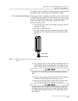
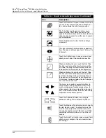
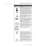
Page 83: ...s When the arrow points to the waste can the valve is set to route fluids to waste This region of the display reports the current tube position on the top line The bottom line reports the maximum number of tubes held by the rack or a user specified number of tubes see page 3 4 Touch the Next Tube icon to advance the drop for mer to the next tube position Touch the Play icon from the main menu to s...

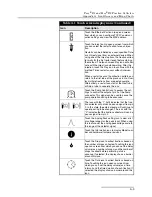
Page 84: ... configuration When calibrating the arm touch the Last Tube Position icon to move the drop former over the last tube The drop former will move to the last tube position for the current rack configuration On two rack fraction collectors the last tube posi tion is on the second rack The Arrow icons perform several functions In some screens the up and down arrows incre ment and decrement alphanumeric...

Page 85: ... 2 of the Pump connector This signal can be used to pause the pump operation during tube advances The icon with the 1 left indicates that the frac tion collector will not send a pause signal from pin 2 In this state the external pump will continue to operate during tube changes The icon with the 0 indicates that the fraction collector will send a pause signal from pin 2 Touch the Analog Peak setti...

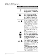
Page 86: ...ut signal exceeds a user set value However the peak state may or may not be true depending on the Threshold Detection Options Touch the Threshold Detection Options icons to select a detection mode The top icon indicates that threshold peak detection is OFF The middle Union icon indicates that threshold peak detec tion is enabled If the value is exceeded the peak state will be true regardless of an...

Page 87: ... or peak width detection condition is true and the time window condition is true the peak state is also true a logical AND Each touch of the Time Windows Start Stop icon advances through the available windows To advance to the next Time Window the current window s settings must have different start and end values Matching values indicates that the previous window is the final time window Start and...

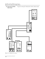
Page 88: ...rts A 6 A 2 Touch Screen Menu Flow Charts Figures A 1 through A 4 illustrate the fraction collector menus Figure A 1 Configuration settings Timed 1200 2400 4800 9600 19200 38400 57600 115200 100 mV external None Inject overlay Inject next Inject skip 99 h 59 m 59 s 1000 mV 10 mV ...

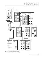
Page 89: ...arts A 7 Figure A 2 Configuration settings continued None 12mmx144 13mmx144 16mmx100 18mm x72 MiniVial 25mm x36 28mm x36 100 IP 1 202 192 168 IP MASK 255 0 255 255 MAC 00 00 00 00 17 8b SERIES 3870 010 REV x FIRMWARE n nn nn 13mmx144 none IP MASK 255 0 255 255 IP 1 202 192 168 ...

Page 90: ...nd Foxy R2 Fraction Collectors Appendix A Icon Glossary and Menu Charts A 8 Figure A 3 Programming displays for the current method __1 20s __m __h _32 0h 0s 1m _10 __h 20s __m __h 30s _3m __h _0s _2m To Fig A 4 ...

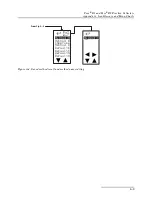
Page 91: ... R2 Fraction Collectors Appendix A Icon Glossary and Menu Charts A 9 Figure A 4 Saved method recall and method name editing Method A 16mmTube Method D DefaultE DefaultF DefaultG DefaultH Method A Method B From Fig A 3 ...

Page 92: ...Foxy R1 and Foxy R2 Fraction Collectors Appendix A Icon Glossary and Menu Charts A 10 ...

Page 93: ...g 4 9 syntax 4 2 communications ethernet 4 1 RS232 serial 4 1 configuration settings 3 3 connections diverter valve 2 5 2 7 drip tray drain tubing 2 9 electrical 1 8 to 1 11 fluid 2 5 connectors AC mains power 1 8 detector 1 9 ethernet 1 8 pump 1 9 rear panel diagram 1 8 serial RS232 1 10 D damage claims 2 1 5 4 delay volume calculating 3 12 compensation 1 6 detector cable Isco 1 10 non Isco 1 11 ...

Page 94: ...naming a method 3 11 threshold peak detection 3 16 time intervals 3 13 time windows 3 21 time based fractions 2 4 volume pump count settings 3 14 method selection menu 2 3 3 10 settings 3 10 mode computer icon 3 1 local 4 4 remote 4 2 4 4 N next tube option injection or timed restarts 3 9 O OR combined peak detection 3 16 3 18 3 19 output signals connector pins 1 8 to 1 11 pump control setting 3 9...

Page 95: ...d fittings 2 6 2 8 syntax serial commands 4 2 system control options 1 7 T TCP IP settings 3 6 telnet 4 1 temperature operating 1 7 threshold detection general 1 2 settings 3 15 time intervals general 1 2 settings 3 13 time windows general 1 2 menu 3 21 settings 3 20 timed restarts 3 6 tools configuration 3 3 tube advance speed 3 4 tube height maximum 1 6 tube volumes by drop counts 3 12 by pump c...

Page 96: ...Foxy R1 and Foxy R2 Fraction Collectors Index Index 4 ...

Page 97: ...Use Standard Description Severity Applied Performance Criteria EN61000 3 2 2014 Current Frequency Harmonics Class A PASS EN61000 3 3 2013 Voltage Fluctuations and Flicker Class A PASS EN61000 4 2 Electrostatic Discharge Level 2 4kV contact discharge Level 3 8kV air discharge A EN61000 4 3 Radiated RF Immunity 80 MHz to 1000MHz 80 AM at 1kHz Level 2 3V m A EN61000 4 4 Electrical Fast Transient Leve...

Page 98: ......

Page 99: ...ct O ST O Represent the concentration of the hazardous substance in this component s any homogeneous pieces is lower than the ST standard limitation X ST X X Represent the concentration of the hazardous substance in this component s at least one homogeneous piece is higher than the ST standard limitation Manufacturer may give technical reasons to the X marks The Environmentally Friendly Use Period...

Page 100: ......

Page 101: ...fragile items can be sent by insured parcel post PLEASE BE SURE TO ENCLOSE A NOTE EXPLAINING THE PROBLEM Shipping Address Teledyne Isco Attention Repair Service 4700 Superior Street Lincoln NE 68504 USA Mailing Address Teledyne Isco PO Box 82531 Lincoln NE 68501 USA Phone Repair service 800 775 2965 lab instruments 866 298 6174 samplers flow meters Fax Email Sales General Information 800 228 4373 ...

Page 102: ......

Reviews: