C-2
© Teledyne Limited
DPN 402197 Issue 7.1
C.1.2 Connection to the cable
Throughout the length of the cable, the tone-carrying conductor must be insulated from sea water.
Where applicable, provide a good ground connection at the end of the cable farthest from the current
source.
C.1.2.1 Short cables
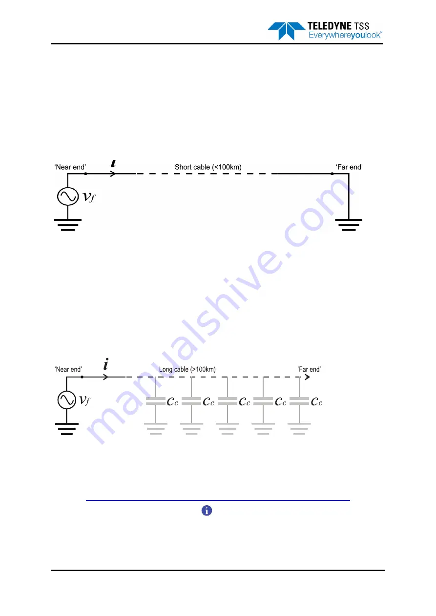
For short cables (of less than approximately 100km, depending upon the capacitance of the cable) you
will need access to both ends of the cable:
Figure C-1: Tone injection – Short cables
You must connect the tone generator
v
f
between the near end of the cable and a good ground point. At
the far end of the cable, you must connect the tone-carrying conductor to a good ground point to
provide an effective signal return path.
C.1.2.2 Long cables
As shown in
, the conductors possess some small capacitance to the environment that
surrounds the cable. If the cable is long (greater than approximately 100km) then the tone signal will
find a return path through the distributed capacitance
C
c
of the cable. The impedance of this path
reduces as the tone frequency increases.
Figure C-2: Tone injection – Long cables
Under these circumstances, it is not always necessary to make a separate ground connection at the far
end of the cable. However, you will reduce the effects of tone leakage by connecting the far end of the
cable to a good grounding point.
NOTE
The capacitance of the conductors extends throughout the length of the cable.
This represents a progressive short circuit that means less tone current flows at
the far end of the cable than at the near end. The detection range of the 350 sys-
tem depends upon the current flowing at the tone frequency. It follows therefore


