2 – Installation
2-14
© Teledyne Limited
DPN 402197 Issue 7.1
2.3.3 Subsea Electronics Pod
CAUTION
While the subsea electronics pod is fused against surges and other over-current
situations, the pod is not a field-serviceable part. Therefore it is the responsibility
of the installer to provide external protection to the system to minimise the risk of
damaging the system.
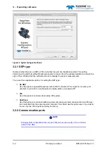
The SEP has six ports that allow connection to the various subsea components of the installation.
On one end cap:
❐
Port coil triad connection
❐
Starboard coil triad connection
On the other end cap:
❐
Power input and communications link
❐
Altimeter connection
❐
Connection for a TSS attitude sensor.
The current version of 350 software does not support
this facility. DO NOT remove the blanking plug from this port.
❐
Auxiliary input connection (for use when you use the 350 System in a Dualtrack installation).
See
for instructions
.
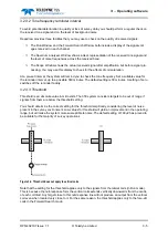
CAUTION
Water could enter the SEP through any port that does not have a connector fitted.
To avoid damage from water ingress, you must fit the correct blanking plug
supplied by TSS to protect any unused port on the SEP.
Tighten the connector locking collars by hand only –
do not over-tighten these connectors
.
2.3.3.1 Power requirement
The SEP requires an electrical supply in the range 110 to 120V a.c. (or 220 to 240V a.c.), 45 to 65Hz to
operate. The maximum current drawn from the supply is 0.3A at 110V (0.1A at 230V) for a stand-alone
350 System, or 3.1A at 110V (1.8A at 230V) if the system is part of a Dualtrack installation.
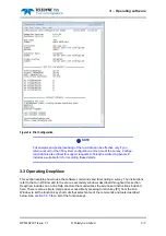
The SEP ‘Power/Comms’ port accepts the electrical supply from the ROV and passes the bi-directional
communications between the SEP and the topside computer. All electrical and communication
connections to the SEP are through the power and communications cable (‘ROV tail’).
the pins of the connector on the power and communications cable, together with the relevant core


