2 – Installation
DPN 402197 Issue 7.1
© Teledyne Limited
2- 19
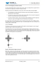
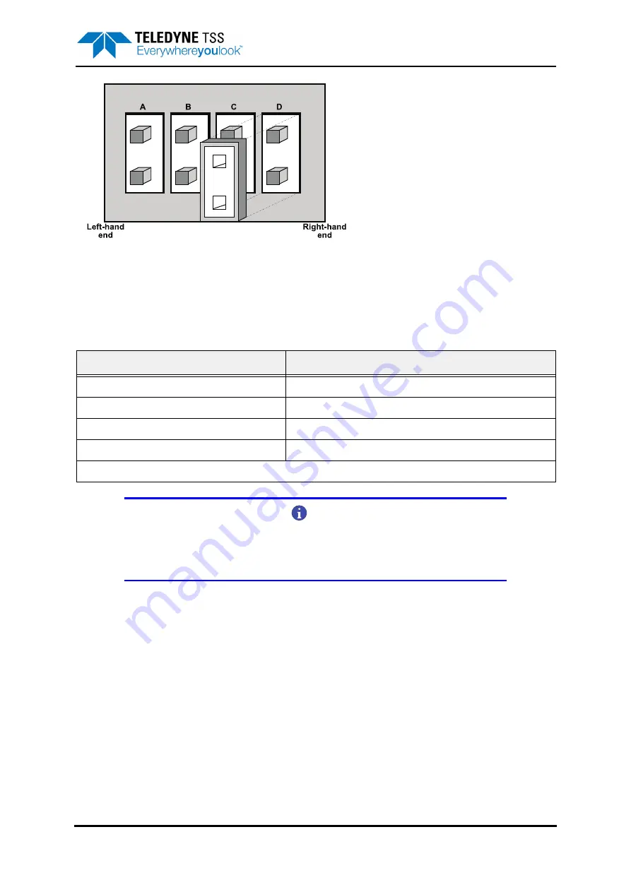
Figure 2-11: Link detail shown using the same orientation as in
The links LK1 to LK5 are identical. Each set of links has a jumper that connects pairs of pins ‘A’ to ‘D’
as appropriate. Remove each of these jumpers from LK1 to LK5 in turn and fit them on the link pins
appropriate for the selected communication method:
NOTE
All five links have the same identification sequence and must be set identically.
DO NOT FORGET to set the jumper on link LK1, which is located away from links
LK2 to LK5 on the board.
Reassemble the SEP:
1. Check the condition of the two rubber O-rings that seal each of the end-caps. Clean or renew
them if necessary. Apply a thin smear of approved lubricant to the rings to ensure they make
an efficient seal when you reassemble the SEP. For this purpose, use the same type of lubri-
cant that you use for the subsea electrical connectors – refer to sub-section
for
instructions.
2. Orientate the circuit board assemblies on the support block:
3. Place the empty SEP housing left-to-right in front of you. Make certain that the short grounding
lead inside the SEP housing is towards the right-hand end of the housing. You must insert the
coil connector end-cap into the housing from the opposite end to the grounding lead.
Table 2-3: Link settings for LK1 to LK5
Communication method
Pin pairs (see
)
RS232
A
RS422 *
B
4-wire 20mA digital current-loop
C
2-wire 20mA digital current-loop (standard)
D
* RS422 communications are not supported by the SDC10.


