6 – Maintenance
6-2
© Teledyne Limited
DPN 402197 Issue 7.1
6.2 Coil Cable Continuity
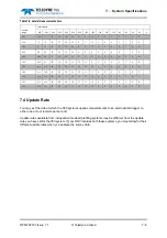
lists the pin-to-pin connections in the coil cables. You may use this information to test the
continuity of the cable during maintenance work.
The two cables are identical. Although you may interchange the coils, you
must
couple the vertical,
lateral and fore-aft coils to their correct 8-way connectors on the cable. Labels identify the cable tails.
6.3 Fault Identification
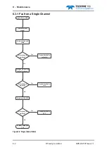
The remainder of this section includes advice and a series of flow charts to help you locate a fault in
the sub-sea components of the 350 system.
NOTE
E
Coil triad cable
F
Coil triad
G
Power and data cable that connects the altimeter to the SEP
H
Subsea altimeter
Table 6-2: Connections to the coil cable
Sensing coil 8-way connector
SEP 12-way connector
Description
Pin
No
Pin
No
Description
G0 – Pre-amp gain control
line
1
1
G0 – Pre-amp gain control line
G1 – Pre-amp gain control
line
2
2
G1 – Pre-amp gain control line
(Lateral)
3
3
Lateral coil
Signal –(Lateral)
4
4
Lateral coil signal –
(Fore-aft)
3
5
Fore-aft coil
Signal –(Fore-aft)
4
6
Fore-aft coil signal –
(Vertical)
3
7
Vertical coil
Signal –(Vertical)
4
8
Vertical coil signal –
+12V supply in
5
9
+12V supply out
–12V supply in
6
10
–12V supply out
Analogue ground
7
11
Analogue ground
12
Screen chassis
Table 6-1: Components of the 350 system
Item
Description

