background image

WaveStation 3000 Function and Arbitrary Waveform Generator

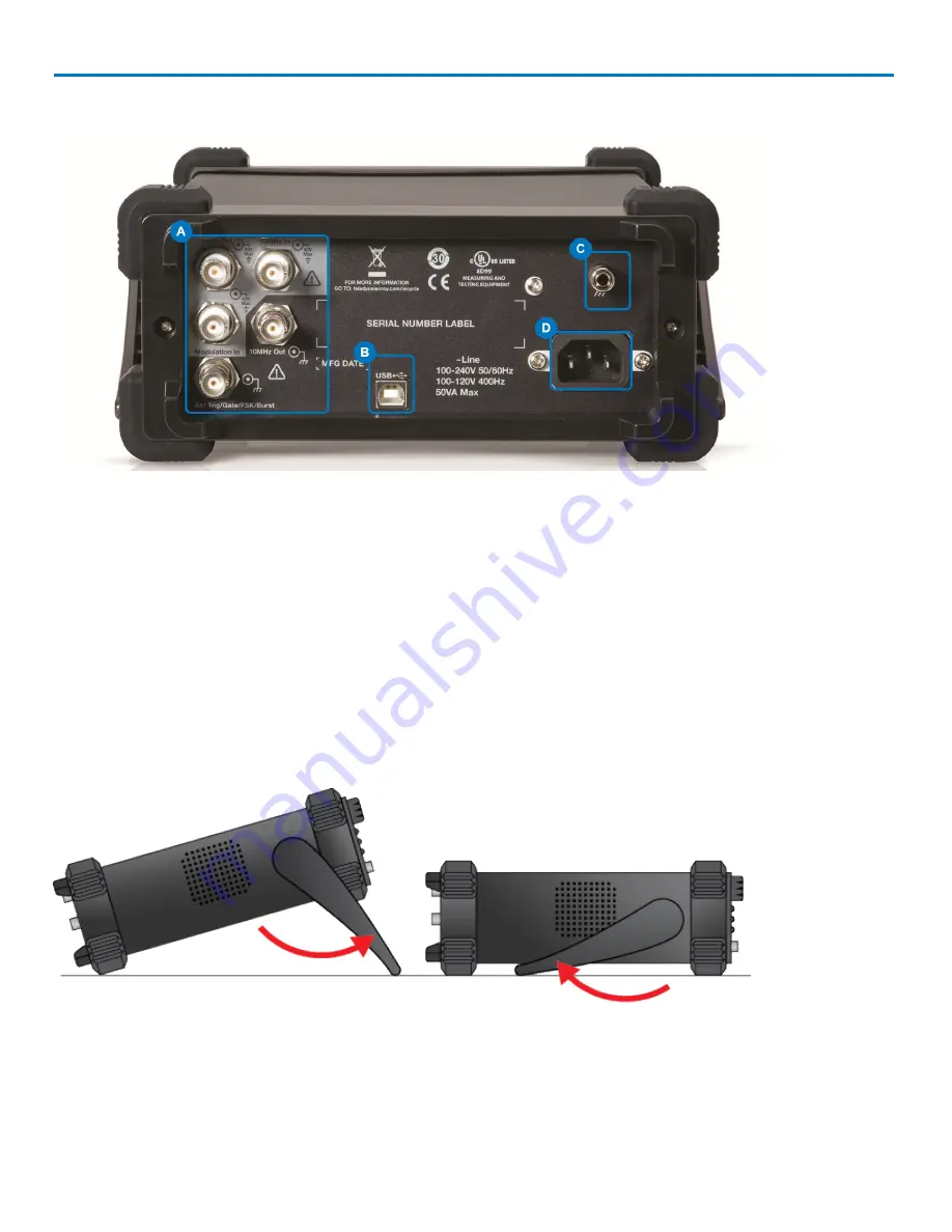
Back Panel

A.

Input and Output BNC Connectors

- provide 10 MHz In, 10 MHz Out,Modulation In, Synch Out, Ext

Trig/Gate/Fsk/Burst Out.

B.

USB Connector

- USB 2.0 Type B, used for making USBRAW or USBTMC connections.

C.

Ground Connector

D.

AC Power Connector

Adjusting the Viewing Position

The built-in carrying handle can be used to support the weight of the product and adjust the viewing position.

Gently pull both arms away from the sides of the WaveStation to unlock the mechanism, then rotate the
entire handle toward you until it snaps into the upright position.

4

922869 Rev B

Summary of Contents for LeCroy WaveStation 3000

Page 1: ...Operator s Manual WaveStation 3000 Function Arbitrary Waveform Generator ...

Page 2: ...tly prohibited However clients are encouraged to distribute and duplicate Teledyne LeCroy documentation for their own internal educational purposes WaveStation and Teledyne LeCroy are trademarks of Teledyne LeCroy Inc Other product or brand names are trademarks or requested trademarks of their respective holders Information in this publication supersedes all earlier versions Specifications are sub...

Page 3: ...ating an AM Modulated Waveform 16 Generating an FM Modulated Waveform 17 Generating a PM Modulated Waveform 17 Generating an FSK Modulated Waveform 18 Generating an ASK Modulated Waveform 18 Generating a DSB AM Modulated Waveform 19 Generating a PWM Modulated Waveform 19 Generating Sweep Waveforms 20 Generating Burst Waveforms 21 N Cycle Burst 21 Gated Burst 22 Using External Trigger 23 Using Sync...

Page 4: ...lling WaveStation PC Drivers and Software 33 Connecting WaveStation to the PC 34 Reading Files from WaveStation on a PC 34 Sending Waveform Files from a PC to WaveStation 37 Save Waveform to CSV File 40 Maintaining WaveStation 41 Cleaning 41 Updating WaveStation Firmware 41 Self Tests 42 Self Calibration 43 Returning a Product for Service 44 Reference 45 Specifications 45 Certifications 45 Warrant...

Page 5: ... Remote control l Using WaveStation PC Software l Changing system settings and other maintenance l Reference including product certifications and Teledyne LeCroy contact information WaveStation can be controlled remotely by an automation device or by a person using the WaveStation PC Software The information in this manual is supplemented by a SCPI Standard Commands for Programmable Instruments Co...

Page 6: ...WaveStation 3000 Function and Arbitrary Waveform Generator iv 922869 Rev B ...

Page 7: ...waveforms seen on the display match the waveforms output by the hardware Graphical Waveform Creation Use WaveStation PC Software to easily create and edit waveforms on your computer using mathematical operations filters and point by point editing or draw a waveform with a mouse Transfer waveforms from the PC to WaveStation over USB then view them on the large display Connect a WaveAce oscilloscope...

Page 8: ...er service center or national distributor if anything is missing or damaged We can only be responsible for replacement if you contact us immediately The standard WaveStation 3000 package includes the following l WaveStation unit l Power Cord l Standard USB 2 0 Type A to Type B Cable 1 m l USB GPIB Converter Cable l WaveStation 3000 Getting Started Guide l Performance Calibration Certificate l Prod...

Page 9: ...lues and change units F Function Buttons open corresponding option menus The top three Signal Conditioning buttons apply Modulation Sweep or Burst to the active waveform Parameter Utility and Help open their respective menus G Waveform Button opens the menu of waveform shapes H Ch1 Ch2 Button selects the output channel and activates the corresponding tab on the display I Adjustment Knob and Left R...

Page 10: ...pe B used for making USBRAW or USBTMC connections C Ground Connector D AC Power Connector Adjusting the Viewing Position The built in carrying handle can be used to support the weight of the product and adjust the viewing position Gently pull both arms away from the sides of the WaveStation to unlock the mechanism then rotate the entire handle toward you until it snaps into the upright position 4 ...

Page 11: ... grounding conductor To avoid electric shock connect only to a grounded mating outlet Connect and disconnect properly Do not connect disconnect probes or test leads while they are connected to a voltage source Observe all terminal ratings Do not apply a voltage to any input C1 C2 C3 C4 or EXT that exceeds the maximum rating of that input Refer to the front of the oscilloscope for maximum input rat...

Page 12: ...sales representative or cutomersupport teledynelecroy com Power AC POWER The instrument operates from a single phase 100 to 240 Vrms 10 AC power source at 50 60 Hz 10 and 100 to 120 Vrms 10 AC power source at 400 Hz 5 Manual voltage selection is not required because the instrument automatically adapts to the line voltage POWER CONSUMPTION 50 VA 50 W maximum power consumption when operating with al...

Page 13: ...to the active waveform The first press of a Signal Conditioning button applies that functionality to the active waveform and opens a menu of corresponding parameters You ll see the name e g Mod for Modulation appear next to the carrier waveform on the Channel tab The second press removes the functionality from the waveform and closes the menu Other Function Buttons The next three function buttons ...

Page 14: ... of options on the display These menus are navigated using the softkey buttons below them Option Menus and Softkey Buttons The softkey buttons correlate with the menu options directly above them which change based on functionality The softkeys behave a bit differently depending on the option They may l Select a numeric parameter for editing on the Parameter Value List l Toggle a set of non numeric...

Page 15: ...parameters that must be configured together For example Amplitude and Offset or HighLevel and LowLevel LABELED MENU OPTIONS Some menu options appear to be dual parameters but actually the top part of the option is a label while the bottom shows the selected value When configuring waveforms this usually indicates the selection was made on a previous menu but is made available again in case you deci...

Page 16: ...stment knob or the numeric keypad Using the Adjustment Knob This is perhaps the easiest way to both select and adjust parameters when configuring waveforms 1 Select the first parameter from the menu using the softkey button The parameter will appear blue on the option menu and white on the Parameter Value list 2 Use the Left Right Cursor buttons to select the digit to change The selected digit is ...

Page 17: ...of measure You will return to the parameter menu 4 Use the softkeys to select the next parameter to edit The Keypad is also used during Self Calibration and Self Test functions Using WaveStation Help Onboard Help provides brief topics to guide you while using the system To use the Help 1 Press the Help function button on the Front Panel to open the Help menu A list of topics appears on the display...

Page 18: ...h you can change this setting on the Utility menu If Channel 1 is correct skip to Step 2 2 Press the Waveform function button to open the Waveform menu then select the desired shape using the softkey The options are Sine Square Ramp Pulse and Noise NOTE The default and min max settings for each waveform depend on your WaveStation model See the specifications maintained on the product datasheet at ...

Page 19: ...he High Level taking up the whole period For Ramp waves also adjust Symmetry For Pulse waves also adjust l Width or Duty Cycle l Rise ing Edge or Fall ing Edge l Delay For Noise waves adjust l Stdev l Mean 4 When all parameters are configured press the appropriate Output button to output the waveform or go on to apply Modulation Sweep or Burst signal conditioning before outputting NOTE Noise waves...

Page 20: ...defaults to the Channel 1 tab and Waveform menu whenever you power on although you can change this settingon the Utility menu If Channel 1 is correct skip to Step 2 2 Press the Waveform function button to open the Waveform menu then press the More 1 of 2 softkey 3 Press the DC softkey 4 Enter the DC Offset value 5 Press the appropriate Output button to output the waveform SEE ALSO Generating Basic...

Page 21: ... press the More 1 of 2 softkey 3 Press the Arb softkey then press the Built in softkey The display changes to show the first group of built in arbitrary waveforms 4 Press the softkeys to select different groups until you find the desired waveform then turn the Adjust knob until the waveform is highlighted white on the LCD 5 Press Done to complete the selection The LCD returns to the regular wavefo...

Page 22: ...on the Channel tab and the modulation parameter menu and value list on the display 3 Press the Type softkey then press the AM softkey 4 Set the following AM parameters l Modulation Source Internal or External If External is selected attach the modulation source to the Modulation In connector on the Back Panel You do not need to set any other parameters l AM Freq modulating waveform frequency The i...

Page 23: ... and 10 V to the negative selected deviation So a 10 V input results in an output FM deviation equal to the preset FM deviation 5 Press the appropriate channel Output button to begin outputting the waveform Generating a PM Modulated Waveform Modulated waveforms are one part carrier waveform the other modulated In Phase Modulation the phase of the carrier waveform varies with the instantaneous volt...

Page 24: ... MHz You do not need to set Key Freq if using an external modulation source l Hop Freq the desired hop frequency level for variation from the set carrier waveform frequency 5 Press the appropriate channel Output button to begin outputting the waveform Generating an ASK Modulated Waveform Amplitude Shift Keying modulation represents digital data as variations in the amplitude of a carrier wave The ...

Page 25: ...Hz 5 Press the appropriate channel Output button to begin outputting the waveform Generating a PWM Modulated Waveform Pulse Width Modulation is used exclusively with Pulse type waves 1 Generate a carrier wave of type Pulse 2 Before outputting press the Front Panel Mod function button You should see Mod appear next to the car rier wave type on the Channel tab and the modulation parameter menu and v...

Page 26: ...FreqSpan l MidFreq and FreqSpan the frequency that must remain at the center of the sweep and the overall span or range that it may deviate from the MidFreq in either a positive or negative direction l Source choose Internal External or Manual to manually start and stop the sweep If External is selected connect the sweep trigger source to the Trig Gate Fsk Burst connector on the Back Panel l TrigO...

Page 27: ...ry waveform 0 is the first waveform point l Burst Period If using Internal Source enter the length of the burst period NOTE The period time increases if necessary to allow the specified number of cycles in a burst The following formula is applied Burst Period Carrier Period Burst Number l TrigOut Internal and Manual Sources or Edge External Source Choose Up rising edge Down falling edge or Off l D...

Page 28: ...the Burst function button 3 Press the Gated softkey until it is selected 4 Enter the Start Phase value in to define the starting point of the burst The phase varies from 0 to 360 the default setting is 0 For an Arbitrary waveform 0 is the first waveform point 5 Choose either Positive or NegativePolarity 6 Press the appropriate Output button to begin outputting the waveform 22 922869 Rev B ...

Page 29: ...gger is received on the Ext Trig connector Externally Gated Burst Mode If using External Source for a Gated Burst wave the instrument outputs a continuous waveform when the Gate signal is true When the external Gate signal goes false the current waveform cycle completes then the instrument stops while remaining at a voltage level corresponding to the starting burst phase For Noise waveforms output...

Page 30: ...and FSK Modulated keying frequency Sweep TTL level high at start then at a frequency equal to the sweep time Burst level high at start External Gated Burst external gated signal Pulse pulse signal with a fixed positive pulse width more than 50 ns NOTE If an output waveform is inverted the corresponding Sync signal does not also invert To enable disable the Sync signal output 1 Press the Utility fu...

Page 31: ...CD screen when performing Save Recall than when generating waveforms The screen is divided into three principal sections l File name at the top of the display l Drive folder list at the left of the display l File list at the right of the display Switch between the folder and file sections of the display by pressing the Browsersoftkey on the Save Recall option menu Scroll each list using the Adjust...

Page 32: ... Press the Utility function button then press the Store Recall softkey 3 Press the FileType softkey until State is selected 4 WaveStation defaults to the Local C folder If using an external drive press the Browser softkey until Directory is selected then turn the Adjust knob until USB Device is selected Otherwise skip this step 5 Press the Browser softkey to select File The cursor switches to the ...

Page 33: ...veform files 7 Turn the Adjust knob until the desired cell file is selected NOTE If possible choose an empty cell when saving a file Any prior data saved in that location will be overwritten 8 Press Save to store the file or Recall to output it using WaveStation NOTE 512K files must be output via Channel 2 9 When saving data files use the keyboard to change the File Name Delete Setup or Waveform F...

Page 34: ...s selected 4 Press Polarity to select either Normal or Invert 5 Press Done USB Output The USB Type B port on the back of the WaveStation can be configured to output either l USBRAW l USBTMC used for remote control and WaveStation PC software 1 Press the Utility function button 2 Press the Interface softkey 3 Press the USB Setup softkey 4 Press either USBRAW or USBTMC 5 Press Done Number Format 1 P...

Page 35: ...there is no activity for 15 minutes To change this setting 1 Press the Utility function button 2 Press the More softkey then press System 3 Press More then press ScrnSvr 4 Choose another time out value from the menu or Off to disable this feature 5 Press Cancel to return to the previous menu then press Done NOTE Only the LCD is disabled after the time out to preserve the display The WaveStation co...

Page 36: ... reset to the CH1 Sine wave parameter menu SubSystem Parameter Default Values Output Function Sine Wave Frequency 1 kHz Amplitude Offset 100 mVpp 0 V DC Phase 0 Terminals High Z Modulation Carrier 1 kHz Sine Wave Modulating 100 Hz Sine Wave AM Depth 100 FM Deviation 500 Hz Key Freq 100 Hz FSK Hop Frequency 1 MHz Phase Deviation 180 Sweep Start Stop Frequency 100 Hz 1 9 kHz Sweep Time 1 S Trig Out ...

Page 37: ...tation provides all necessary power to the converter To utilize GPIB remote control l Prepare your control files according to the conventions documented in the WaveStation SCPI Command Reference l Connect the USB GPIB converter cable l Configure the WaveStation for GPIB communication Connecting the USB GPIB Converter Connect the USB GPIB converter from the USB A port on the front of the WaveStatio...

Page 38: ...ort on the back of the WaveStation to a USB A port on the controller l Configure WaveStation for USBTMC output Using LabView Software Either the USB or GPIB interface can be utilized with the free LabView Driver to remote control the WaveStation using LabView projects The download includes three sample LabView projects that you can use to set up your own LabView workflow Waveform files saved in th...

Page 39: ...ation PC drivers and software 1 Download the latest version of WaveStation PC Software compatible with your WaveStation model from tel edynelecroy com Unzip the installer archive on the PC where you will install the software 2 With both the WaveStation and the PC turned on connect the 1 m USB 2 0 Type A B Cable from the USB B port on the back of the WaveStation to a USB A port on your PC If shown ...

Page 40: ...rm file from the WaveStation and send it to the WaveStation PC software for modification Complete the preliminary steps to l Install WaveStation PC drivers and software l Make the connection from WaveStation to the PC Starting from WaveStation 1 Follow the steps to generate an arbitrary waveform choosing either one of the Built In or Stored Wforms 2 In the WaveStation PC Software choose Communicat...

Page 41: ...y the file as desired Starting from the PC 1 Click the Read wave button on the lower part of the screen 2 On theRead wave pop up select the desired waveform from the Wave List This list will include the names of all the built in arbitrary and saved waveforms 922869 Rev B 35 ...

Page 42: ...WaveStation 3000 Function and Arbitrary Waveform Generator 3 Use the PC software tools to modify the file as desired 36 922869 Rev B ...

Page 43: ...1 Launch the WaveStation PC Software and select File New from the menu bar The Property setting pop up is shown 2 Provide a name for you Wave and details for l Samples choose either 16k or 512k the file will be stored in the respective bank l VPP defaults to 20 Vpp l Quantify defaults to 14 l Frequencyor Period of the waveform Click the Ok button when finished NOTE Vpp can be changed in the next s...

Page 44: ...appears on screen Use the Waveform Type buttons or using various Waveform Drawing Tools to modify it as desired 4 With your waveform setup as desired click Save 5 Choose Communication Send wave from the menu bar or click the Send wave button at the bottom of the window 38 922869 Rev B ...

Page 45: ...Name of the file l Transfer channel 512k files can only be sent over CH2 Click Send A status message should appear indicating the read completed successfully NOTE When you save a data file to a location already containing previously stored information your new information always overwrites the old If you choose the wrong bank or transfer channel for the size of the file you ll see the following er...

Page 46: ...l usual waveform parameters such as frequency ampli tude etc in a comma delimited file The file header shows the saved data l SendWave CSV includes just the amplitude data in a format that can be exchanged with LabView software To save a waveform 1 Choose File Save 2 Browse to the folder where you wish to save the file 3 Enter a File Name 4 Chose to Save as Type CSV or SendWave CSV 5 Click Save 40...

Page 47: ...rary waveform generators from teledynelecroy com support softwaredownload To install firmware updates 1 Extract the firmware file filename ads and save it to a USB drive 2 Power on the WaveStation and plug the USB drive into the Front Panel USB port 3 Press the Utility function button then press the More and Update softkeys 4 You ll see the Browser display used to Save Recall files Press the Brows...

Page 48: ...ration of the LCD 1 Press the Utility function button 2 Press the More softkey then press Test Cal 3 Press SelfTest then ScrTest You will see the display change to red 4 Following the directions on the display continue to press the number 7 on the keypad to cycle through red green and blue Press the number 8 on the keypad to exit the test Key Test This test determines if the WaveStation CPU is rec...

Page 49: ... in the Key Test 4 Continue to press the number 7 on the keypad Each block on the simulation that corresponds to a Func tion button turns blue while the button itself lights up indicating proper functioning If any block or button fails to light the control is malfunctioning 5 Press the number 8 on the keypad three times to exit the test Self Calibration WaveStation includes a self calibration rout...

Page 50: ...a tag containing l The RMA l Name and address of the owner l Product model and serial number l Description of failure or requisite service 4 Pack the product case in a cardboard shipping box with adequate padding to avoid damage in transit 5 Mark the outside of the box with the shipping address given to you by Teledyne LeCroy be sure to add the following l ATTN RMA code assigned by Teledyne LeCroy...

Page 51: ...N 61000 4 3 2006 RF Radiated Electromagnetic Field 3 V m 80 1000 MHz 3 V m 1400 MHz 2 GHz 1 V m 2 GHz 2 7 GHz 4 EN 61000 4 4 2004 Electrical Fast Transient Burst 1 kV on power supply lines 0 5 kV on I O signal data and control lines 4 EN 61000 4 5 2006 Power line Surge 1 kV AC Mains L N L PE N PE 4 EN 61000 4 6 2007 RF Conducted Electromagnetic Field 3 Vrms 0 15 MHz 80 MHz 4 EN 61000 4 11 2004 Mai...

Page 52: ...se Part 1 General requirements EN 61010 2 030 2010 Safety requirements for electrical equipment for measurement control and laboratory use Part 2 030 Particular requirements for testing and measuring circuits The design of the instrument has been verified to conform to the following limits put forth by these standards l Overvoltage Category II equipment intended to be supplied from the building wi...

Page 53: ...66 EC on Waste Electrical and Electronic Equipment WEEE and Batteries The instrument is subject to disposal and recycling regulations that vary by country and region Many countries prohibit the disposal of waste electronic equipment in standard waste receptacles For more information about proper disposal and recycling of your Teledyne LeCroy product please visit teledynelecroy com recycle RESTRICT...

Page 54: ...our authorized service centers within this period However in order to do this we must first examine the product and find that it is defective due to workmanship or materials and not due to misuse neglect accident or abnormal conditions or operation Teledyne LeCroy shall not be responsible for any defect damage or failure caused by any of the following a attempted repairs or installations by person...

Page 55: ...irect teledynelecroy com teledynelecroy com europe Protocol Analyzers Ph 44 12 765 03971 Singapore Oscilloscopes Teledyne LeCroy Singapore Pte Ltd Blk 750C Chai Chee Road 02 08 Technopark Chai Chee Singapore 469003 Ph 65 64424880 FAX 65 64427811 Singapore Protocol Analyzers Genetron Singapore Pte Ltd 37 Kallang Pudding Road 08 08 Tong Lee Building Block B Singapore 349315 Ph 65 9760 4682 China Tel...

Page 56: ...ypad 11 LED test 43 softkeys 8 sync signal 24 cooling 6 D DC wave 14 display 8 keyboard 25 number format 28 screen test 42 store list 25 E external trigger 23 F firmware 41 front panel 3 function buttons 7 G gated burst 22 23 GPIB 31 H handle adjusting 4 help 11 I inputs outputs 3 4 23 24 M modulation AM 16 ASK 18 DSB AM 19 FM 17 FSK 18 23 PM 17 PWM 19 N N cycle burst 21 23 navigation 8 noise wave...

Page 57: ...7 33 34 37 screen saver 29 self tests 42 key test 42 LED test 43 screen test 42 setups 26 copy 27 default 30 power on setting 29 utilities 28 sine wave 12 sound 29 specifications 1 45 square wave 12 support help 11 sweep wave 20 23 sync signal 24 U USB 28 32 V viewing position 4 voltage 28 W warranty 48 waveform arbitrary 15 burst 21 DC 14 noise 12 pulse 12 ramp 12 save recall 27 34 37 sine 12 squ...

Page 58: ......

Reviews: