


©
Page
20
of
28
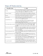
No Power
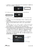
Confirm that the POE Box is plugged into a standard 120 or 220 VAC outlet and
that the small green LED on the POE Box is illuminated. Check that the Sonar-
to-Surface cable is plugged into the
SONAR
J1
port on the POE Box.
Improperly connected
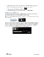
In addition to the connections described above, verify that you have a good
cable between the computer Ethernet port and the
PC
J2
port on the POE Box.
Bad State
Reset the sonar by removing the POE box AC power cord for 10 seconds. The
sonar head takes ~ 40 seconds to reboot after power is re-applied.
Dirty connectors
Make sure that all connector pins are clean and corrosion free.
Improper Ethernet cable
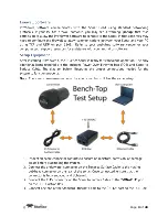
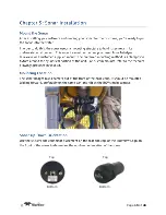
The Sonar Head cabling is conveniently designed so that you can connect your
POE Box to a PC with a
standard
Ethernet cable.
However, when connecting your POE Box to a network hub, a crossover
Ethernet cable is required
unless
your network hardware is capable of
automatically handling crossed Ethernet cables.
PC networking software is confused
Restart the networking software. There are several ways to do this depending
on your particular operating system: Open the windows network connection
window and right click on the Ethernet connection. Select
repair
or
disable
then
enable
. You can also simply restart the computer or cycle the power on
the sonar.
IP subnet masks don’t match
Make sure the subnet mask is
the same
on both PC and sonar. For the factory
default Class C network configuration, the subnet mask is 255.255.255.0. The
255 defines the
network
portion of the IP address. The 0 defines the
device
portion of the IP address.
IP network addresses don’t match.
Make sure the IP
network
part of the IP address is
the same
on both the sonar
and the computer. In the factory default case, this is the first 3 numbers in the
IP address: 192.168.1.
IP network device addresses are the
same.
The
device
part of the IP address must be
different
for every device on the
network. In the factory default case, the sonar is set to 45 and the PC is set to 3.
Do not use 255 as it is reserved for broadcast use.
PC ARP table is stale.
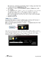
In the ProViewer Sonar Devices window, click the
Add
button and enter the IP
address you think the sonar is set to respond to, then click
OK
. The sonar
should respond within several seconds. Alternatively, the PC power can be
cycled to refresh the ARP table.
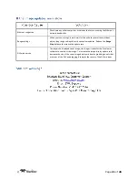
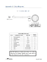
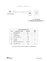
Poor connection quality
Use an ohm meter to verify
Tx
and
Rx
line connectivity between the Ethernet
connector that plugs into the PC and the connector that plugs into the Sonar
Head. Refer to the ProViewer Sonar to Surface Cable Drawing in the Spec sheet
for pin to pin connection information.
Summary of Contents for P series
Page 3: ... Page 3 of 28 2 6 6 7 7 7 8 8 8 9 9 10 11 11 12 12 12 14 15 15 15 15 16 17 17 18 19 19 19 20 ...
Page 4: ... Page 4 of 28 21 21 22 24 24 25 25 26 27 ...
Page 5: ... Page 5 of 28 ...
Page 6: ... Page 6 of 28 ...
Page 7: ... Page 7 of 28 ...
Page 8: ... Page 8 of 28 ...
Page 9: ... Page 9 of 28 ...
Page 10: ... Page 10 of 28 Connect ...
Page 11: ... Page 11 of 28 ...
Page 12: ... Page 12 of 28 ...
Page 13: ... Page 13 of 28 RJ11 Connector To the Sonar Power Cable Plug PC link VDSL link to sonar Power ...
Page 14: ... Page 14 of 28 Connect ...
Page 15: ... Page 15 of 28 Top Top Bottom Bottom ...
Page 16: ... Page 16 of 28 Target Depth ft 0 10 20 30 40 60 80 Approx Tilt Angle Deg 0 3 8 10 10 15 20 ...
Page 17: ... Page 17 of 28 ...
Page 18: ... Page 18 of 28 ...
Page 19: ... Page 19 of 28 ...
Page 24: ... Page 24 of 28 ...
Page 25: ... Page 25 of 28 ...
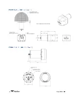
Page 26: ... Page 26 of 28 Units Inches ...


