Appendix A
Technical Specifications
139
•
Temperature Stability: ±0.05°C; closed-loop stabilized-temperature control
•
Gain: Software-selectable [1 (low), 2 (medium), 3 (high)]
•
, on page 141
•
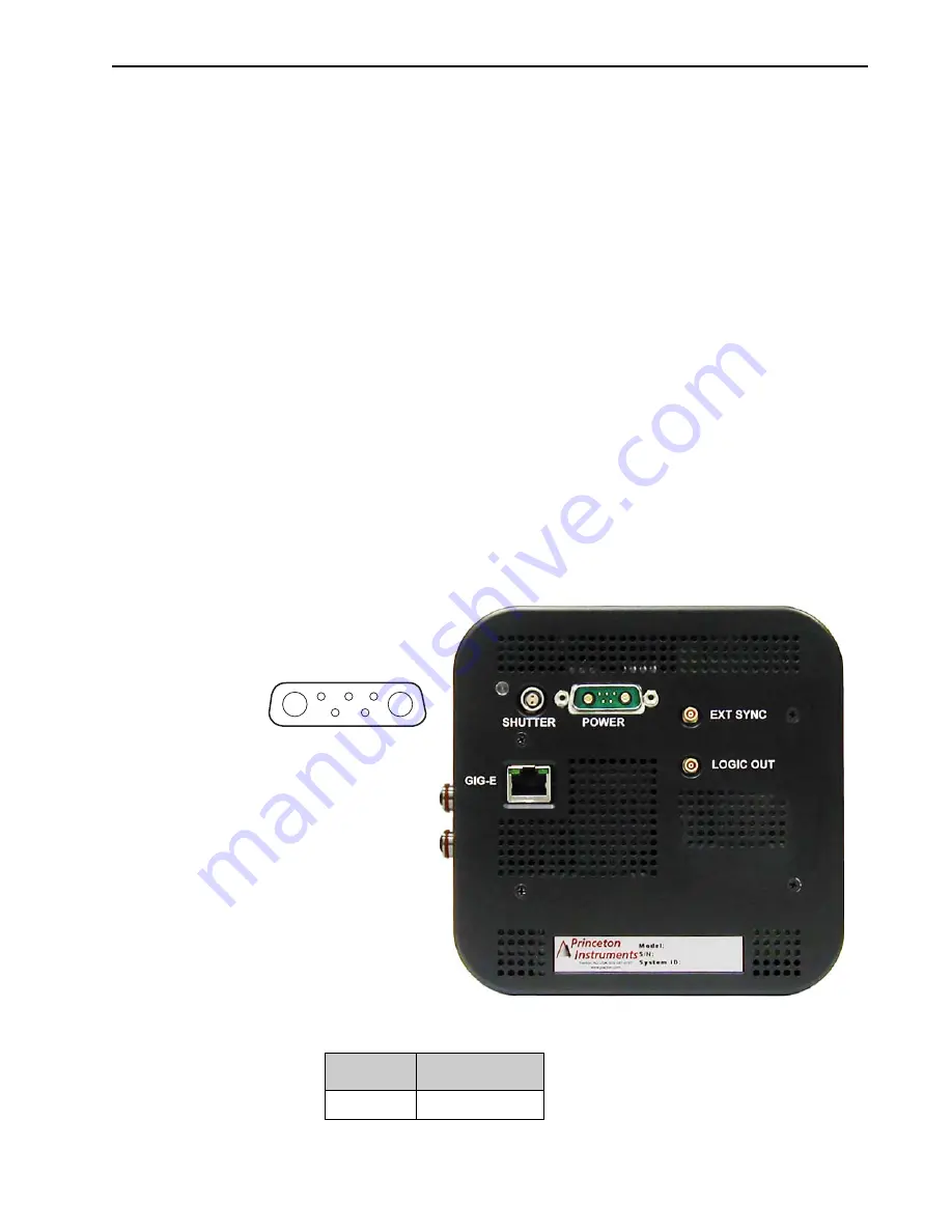
Connectors:
— Gig-E: Gigabit Ethernet connector.
— Shutter: LEMO
®
connector provides the shutter drive pulses for driving a
Teledyne Princeton Instruments-supplied 25 mm external shutter in lieu of
integrated shutter. Camera power must be OFF before connecting to or
disconnecting from this connector. Cable not supplied.
•
When there is an installed internal shutter, this connector cannot drive an
external shutter.
•
Ext Sync: 0 to +3.3 V logic level input to allow data acquisition to be
synchronized with external events. Trigger edge can be positive- or
negative-going as set in software. Synchronization and Timing Modes are
discussed in
. MCX-to-BNC adapter cable is
supplied with system.
•
Logic Out: 0 to +3.3 V programmable logic level output (TTL-compatible). The
output of this connector can be programmed and can also be inverted via the
application software. For detailed information about each output signal, refer to
Section 6.3, LOGIC OUT Control
•
Power Connector:
shows the Power Connector on the rear panel of the ProEM camera,
including the pinout diagram. Refer to
Table A-3, Power Connector Pinout
pin assignment information.
Figure A-1: Rear of ProEM Camera
Table A-3: Power Connector Pinout (Sheet 1 of 2)
Pin #
Signal
A1
TEC Return
A2
A1
5 4 3
2 1
4
4
11
-0
126
_
004
6
441
1-
0
12
6
_
0
0
9
4
Summary of Contents for ProEM Series
Page 1: ...www princetoninstruments com ProEM System Manual 4411 0126 Issue 3 September 26 2019 ...
Page 10: ...10 ProEM System Manual Issue 3 This page is intentionally blank ...
Page 16: ...16 ProEM System Manual Issue 3 This page is intentionally blank ...
Page 30: ...30 ProEM System Manual Issue 3 This page is intentionally blank ...
Page 50: ...50 ProEM System Manual Issue 3 This page is intentionally blank ...
Page 88: ...88 ProEM System Manual Issue 3 This page is intentionally blank ...
Page 114: ...114 ProEM System Manual Issue 3 This page is intentionally blank ...
Page 122: ...122 ProEM System Manual Issue 3 Figure 7 8 LightField Settings 4411 0126_0078 ...
Page 136: ...136 ProEM System Manual Issue 3 This page is intentionally blank ...
Page 146: ...146 ProEM System Manual Issue 3 This page is intentionally blank ...
Page 152: ...152 ProEM System Manual Issue 3 This page is intentionally blank ...
Page 161: ...This page is intentionally blank ...


